PAL-AT Installation Manual
54
8.3.3 Cable Types JMP-U/-UD, JPP and JMP
Step A Install connectors and test them following the "Cable and Connector Testing Procedures" in this
manual.
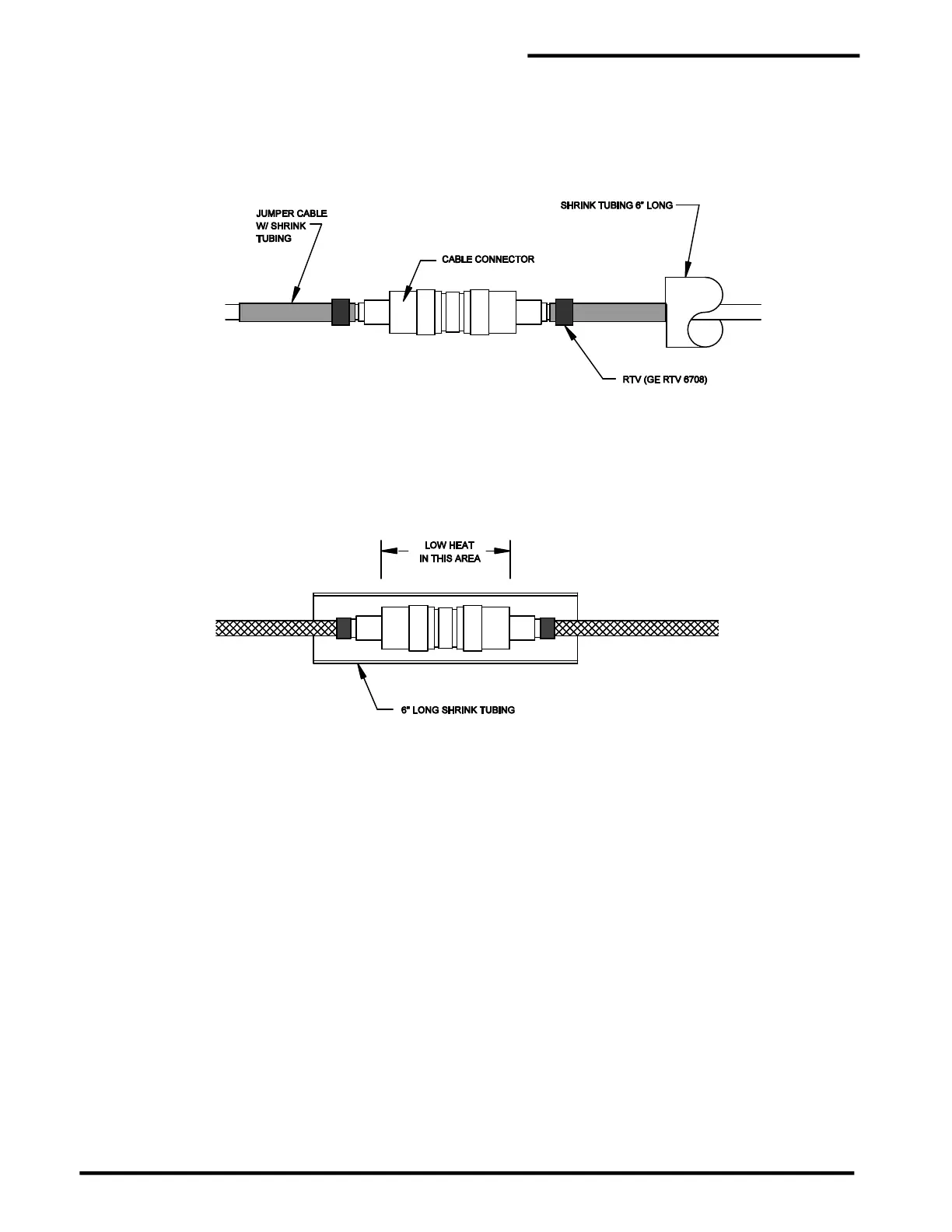
Step B Slide a 6" [150 mm] piece of shrink tubing on the cable and tighten the connector assembly
securely.
Apply a minimum ¼" [6 mm] bead of noncorrosive type RTV completely around the cable on
the installed shrink tubing next to the end of each of the connectors.
Step C Center the 6” long shrink tubing over the connector. Carefully heat the tubing, slightly, over the
center of the connector. Caution: If the shrink tubing is overheated in the center area, it may
tear as it tries to shrink to the size of the cable. Next heat the remainder of the tubing. Do
not heat the tubing any longer than required to shrink the tubing around the cable.
8.4 Cable and Connector Testing Procedures
8.4.1 General
The following tests should be performed on each length of cable after both connectors are installed. Figure
8-1 illustrates the tests. Any overbraid or outer jacket is not shown.
8.4.2 Continuity Test
The continuity test checks for broken cable, open connectors, and poor connections.
1. Connect a short jumper wire with alligator clips between the UHF connector’s center contact and the
body of the connector at one end of the cable, as shown in figure 8-1. Note: Do not clip onto the
threaded coupling ring because the ring is not tightly secured, resulting in intermittent
readings.
2. Connect the ohmmeter's test leads to the connector’s center contact and connector body on the other
end of the cable.
3. The ohmmeter reading should be less than 10 ohms/1000' [10 ohms/300 m] of cable. If it is not, check
the jumper wire, test lead connections, and repeat the test. If the problem persists, contact the
PermAlert Field Service Department for assistance.