PAL-AT Installation Manual
44
8 Cable Connectors
8.1 General
This section outlines: (1) the installation procedures for several types of connectors; (2) the application of
shrink tubing; and (3) the electrical testing of connectors and cable. All connectors are crimp style and
soldering is not required.
Instructional videos for Cable Connector Installations are available at the PermAlert web site,
www.permalert.com.
WARNING For Hazardous Locations – Some cable connectors are located in NEMA 4X [IP66]
junction boxes that are made of plastic and as such, present a possible electrostatic hazard. They
are not intended to be cleaned, but if they are, a damp cloth should be used.
8.2 Cable Connector Installation
1. Cable connectors must be installed at changes of cable types, pull points, junction boxes, calibration
points, and at the termination of the sensing string.
2. All the PAL-AT cables, except ATP, are coaxial construction consisting of an insulated center conductor
and a braid shield. Jumper cables and TFH sensor cable have a polymer jacket over the braid. All
coaxial sensor cables also have a polymer overbraid surrounding the cable.
3. Crimp style connectors are required for all sensor cables and all jumper cables.
4. TFH sensor cable ends must be kept dry and encapsulated in shrink tubing until the connectors
are installed. Connectors that become calibration points during the commissioning of the
system should not be installed prior to commissioning, if they cannot be kept dry. Install the
shrink tube caps, included with the connectors, on the end of the cables temporarily.
8.2.1 CAGOLD and CATFH Connectors for Sensor Cables
AGW-Gold, AGT-Gold, TFH-Gold and TFH
The CAGOLD connector assembly for AGW-Gold, AGT-Gold and TFH-Gold consists of two crimp style
UHF plugs, two #14 AWG wire ferrules, one UHF straight adapter, and one piece of shrink tubing. The
CATFH assembly for TFH includes the same connectors and 3 pieces of shrink tubing. Steps A thru I
must be followed to install a connector.
Step A Measure and cut the required length of cable.
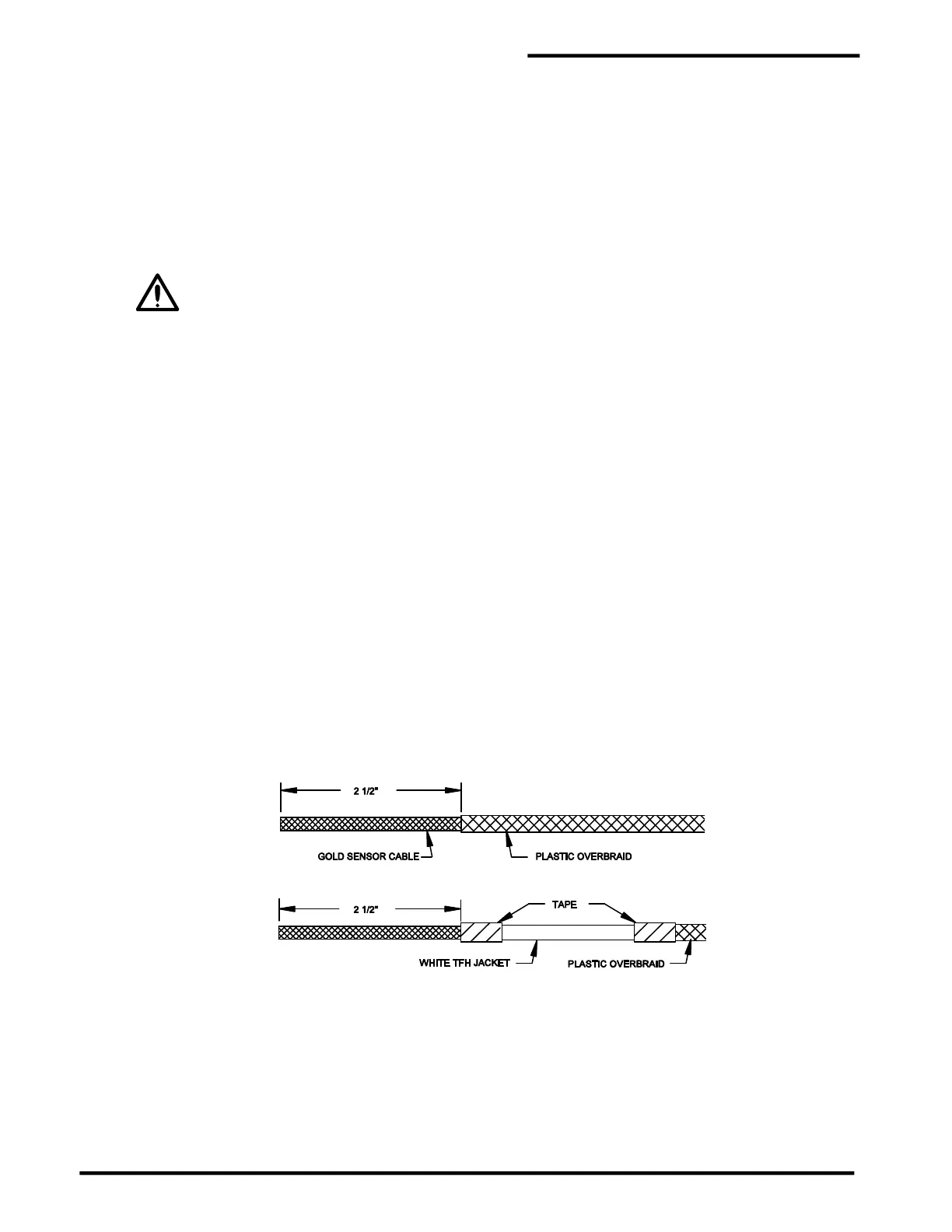
Step B Carefully cut and remove 2½" [65 mm] of the plastic overbraid. It may be helpful to slide the
remaining overbraid back several inches and use electrical tape to hold it in place out of the way.
TFH cable has a white outer jacket under the overbraid. Remove 2 ½” [65 mm] of the white jacket.
Step C Skip this step for TFH cable. A sanding tool (included with the purchase of a crimp tool) is inserted
into the cable. The tool is a 6" [150 mm] length of stainless steel tubing.
For AGW-Gold, insert the center conductor and two plastic spiral spacers into the end of the tool.
Then slowly rotate the tool counterclockwise and gently push the tool 3" [75 mm] into the cable
underneath the braid wire.
For TFH-Gold, insert the center conductor and the white core into the end of the tool. Then slowly
rotate the tool and gently push the tool 3" [75 mm] into the cable underneath the braid wire.