PAL-AT Installation Manual
48
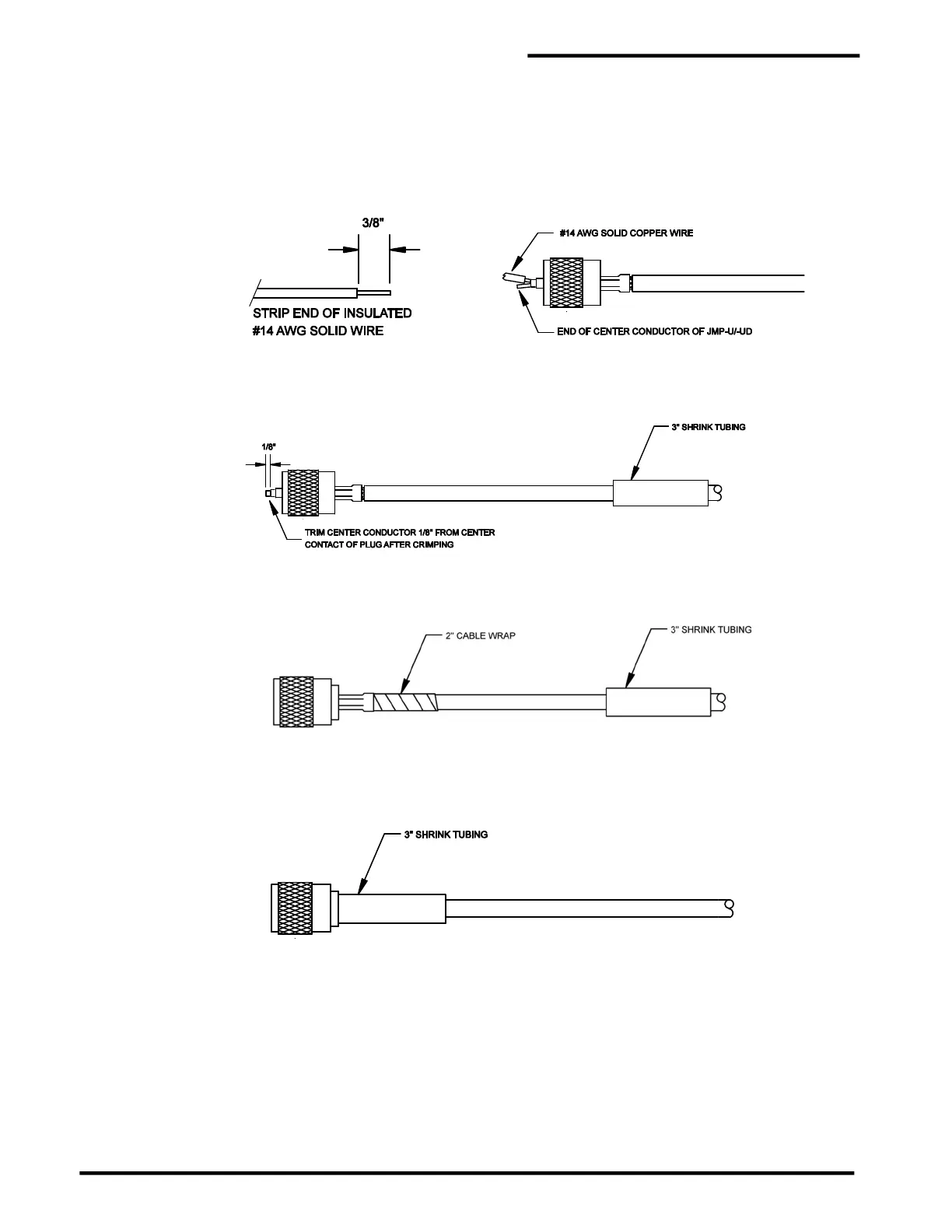
The procedure for crimping the center conductor requires a short length of #14 AWG solid copper
wire to fill the center contact of the connector. Strip 3/8” of insulation from the wire. Bend the end
of the strands of the center conductor slightly to the side. Next, carefully slide the bare #14 AWG
wire all the way into the center contact as shown. The #14 wire should be inserted next to the
JMP-U conductor and not into the strands of the conductor. Be careful so the strands of JMP-U
do not slide into the connector with the #14 wire. Crimp the center contact as shown using a
0.100" die.
Step F Trim any center conductor (and #14 AWG wire, if applicable) extending out of the center contact
of the plug. Thread the UHF coupling ring onto the UHF plug body.
Step G Place a 2” piece of plastic cable wrap around the cable jacket and slide it under the uncrimped
end of the outer ferrule as far as possible.
Step H Slide the 3” [75 mm] piece of shrink tubing over the crimped outer ferrule until it completely covers
the ferrule. Make sure the shrink tubing does not slide onto the plug body. Heat the shrink tubing
with a heat gun until it has fully shrunk and adhesive oozes out the end. Let the assembly cool
before handling.
Test all connections as described in the “Cable and Connector Testing Procedures” section. Each
end of the cable in the stage shown above will be fastened together by using one UHF straight
adapter. All cable connectors should be encapsulated with non-corrosive RTV sealant and shrink
tubing.