PAL-AT Installation Manual
76
9. Try to pull the splice apart with 10-25 lb [4.5-11 kg] force to ensure the wires were correctly seated in
the connector.
10. Repeat steps 3-9 for the white wire. The red and white wires must be twisted with a 2” – 3” [50-75
mm] pitch throughout the splice area before crimping the second connector.
11. Slide the 2 pieces of shrink tubing over the splices and shrink the tubing. There should be no copper
wire exposed after the tubing shrinks. If so, the connector should be replaced.
12. There should not be gaps between the red and white twisted wires. If they are not in contact
with each other, twist the wires slightly to eliminate any gap.
13. Test each wire for continuity and insulation as described above.
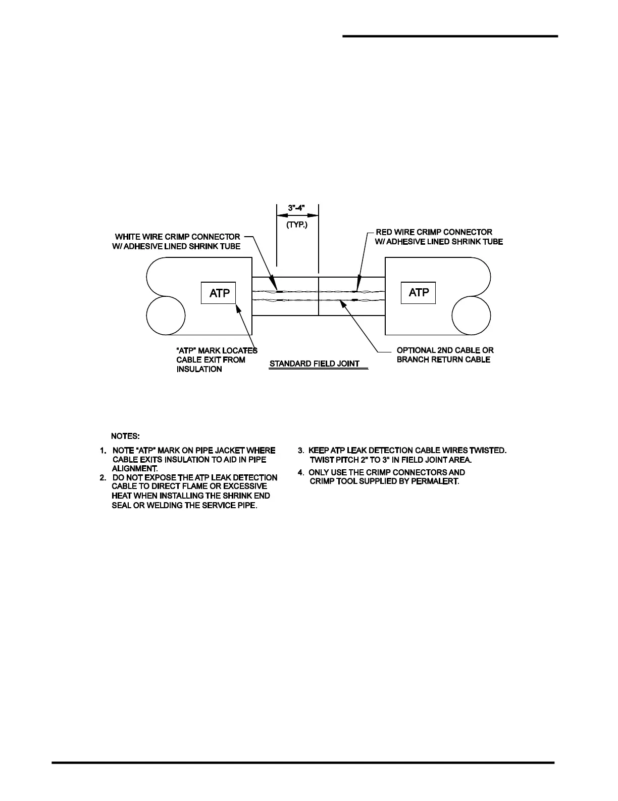
Figure 10-2
ATP Connection Details