Instruction manual for use and maintenance
for WM1L/S WM1L/S-M WM1L/E Single
head machines
File: 1927.doc - 25/01/02 11:55
20
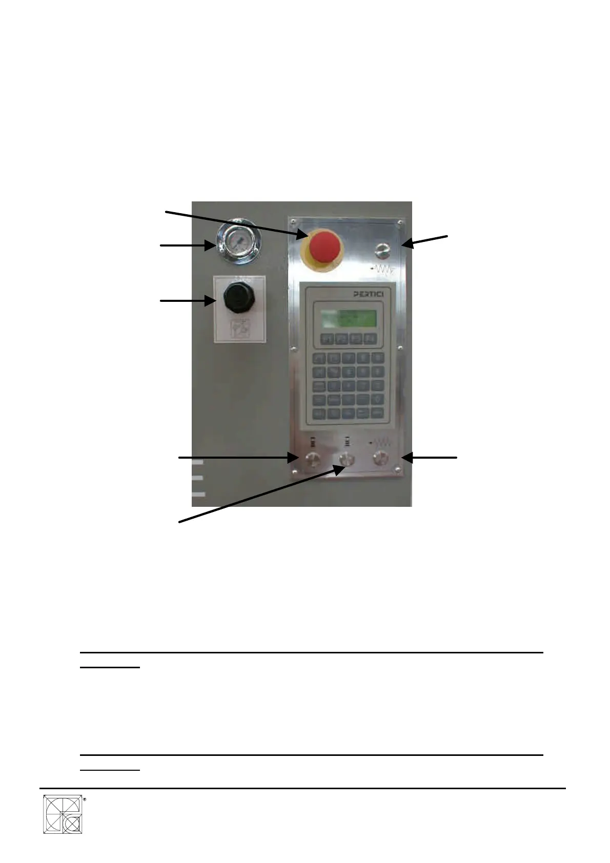
MAIN SECTION SWITCH (DWG. A1.15)
Turning the main section switch to position 1 the machine is energised.
To open the electric cabinet, the section switch must be turned to position 0.
EMERGENCY PUSH BUTTON (DWG. A1.16)
The push button for the emergency stop is easy recognisable thanks to the characteristical red
mushroom shape. The push button is of the type with “mechanical hook-up“: to bring it back to
working conditions pull the mushroom in the operator direction.
DWG. A1.16
LEFT/RIGHT LOCKING/UNLOCKING PUSH BUTTON (DWG. A1.16)
The PBSX PBDX push buttons are used to activate the locking cylinders for locking of
pieces on the working surface.
These push buttons must be kept pressed during the lowering of the locks.
ATTENTION: IN CASE OF REPLACEMENT USE ONLY PERTICI ORIGINAL PUSH
BUTTONS
BI-MANUAL PUSH BUTTONS P1 P2 (DWG. A1.16)
The P1 and P2 push buttons are used to start the working cycle and afterwards to carry
out the automatic welding cycle.
The push buttons must be pressed at the same time (maximum delay 0.5 seconds).
ATTENTION: IN CASE OF REPLACEMENT USE ONLY PERTICI ORIGINAL PUSH
BUTTONS
EMERGENCY
PUSH BUTTON
(PE)
P1 PUSH
BUTTON (BI-
MANUAL)
P.B. FOR
LOCKING/UNLOCKING OF
LEFT PRESSOR PBSX
P2 PUSH
BUTTON (BI-
MANUAL)
P.B. FOR
LOCKING/UNLOCKING OF
RIGHT PRESSOR PBDX
FUSING
PRESSURE
MANOMETER
KNOB FOR
FUSING
PRESSURE