VEHICLERECOVERYANDSPRINGBRAKES
Ifyourvehicleisnotequippedwith
theproperrecoveryhitchassembly,
contactanauthorizeddealertoobtain
theproperequipment.
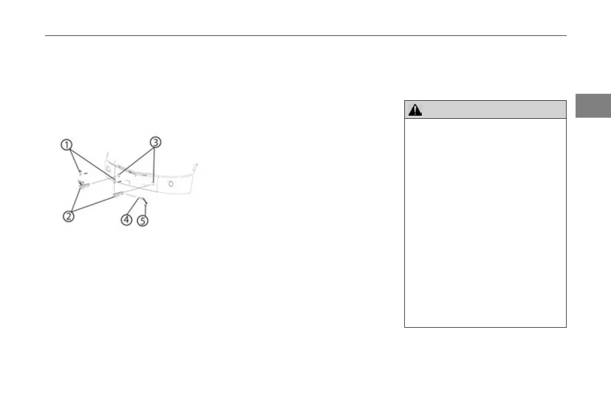
RecoveryHitchAssembly
1TowPin
2TowHitch
3SquareHitchSocket
4LockPin
5LockT ab
RecoveryHitchInstallation
Usethefollowingproceduretoinstall
theVehicleRecoveryHitches.See
RecoveryHitchAssemblyillustration
forpartidentication.
1.Checksquaresocketsbehind
lowerbumperforobstructions,
clearifnecessary.
2.Withlockpinsremoved,insert
hitchesthroughbumperandinto
thesquarehitchsocket.
3.Aligntheholeinthetowhitchwith
thesquarehitchsockethole.
4.Insertthelockpinintothesquare
hitchsocketholeandthrough
theholeinthetowhitchuntilthe
locktabiswithinthesquarehitch
socket.
5.Rotatethelockpin90degreesto
securethepininplace.
6.Removethehitchesandstoreall
partsafterrecoveringthevehicle.
DriverControlledMainDifferential
Followthesestepstolocka
driver-controlledmaindifferential.
WARNING!
Anopenairlineontherecovered
vehiclewillcausealeakintheair
systemoftherecoveryvehicleif
bothvehicles’brakesystemsare
connected.Thiscouldcausealoss
ofsystemair,whichcancausethe
servicebrakesnottofunction,re-
sultinginthesuddenapplicationof
thespringbrakescausingwheel
lock-up,lossofcontrol,orovertake
byfollowingvehicles.Youcould
beinanaccidentinvolvingdeath
orpersonalinjury.Ensurethatany
airlinethathasbeenremovedfrom
adriver-controlledmaindifferential
lockisrmlycappedtopreventloss
ofairpressurefromtherecovery
vehicleifitissupplyingairpressure.
(03/17)Y53-6060-1C12-15
2