Access: Menu [Measurement] [Set points] Choice -
Setting limit
1)
Other set
points
To be set
4 additional hard vacuum reject points (reject point #2/3/4/5), managed by the communication
interface (see the operating instructions for the interface (see chapter “Applicable Docu-
ments”)), are available.
The function is only available with the ‘hard vacuum’ test method.
Detector equipped with 37-pin I/O communication interface (option/accessory).
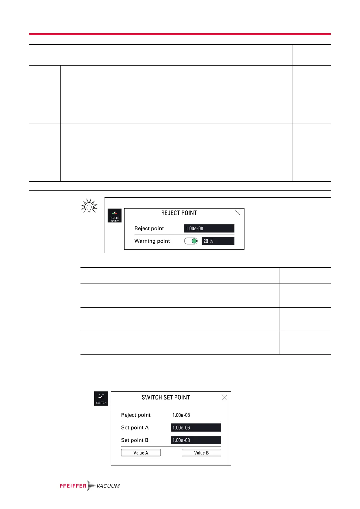
Example: reject point = 5 · 10
-5
-> if 20%, warning point = 1 · 10
-5
5 · 10
-5
– 3 · 10
+2
1 · 10
-12
–
1 · 10
+06
Other
pressure
set points
To be set
2 additional pressure set points (pressure set point #1/2), managed by the communication in-
terface (see the operating instructions for the interface (see chapter “Applicable Docu-
ments”)), are available.
The function is only available with the ‘hard vacuum’ test method.
Detector equipped with 37-pin I/O communication interface (option/accessory).
Installation equipped with an external gauge (customer’s responsibility)
Pressure reject point 1 must always be greater than pressure reject point 2
1 · 10
-19
–
1 · 10
+19
1) Initial setting: see chapter “Tree diagram to the Settings menu”
For quick access from the main screen, use the [REJECT POINT] function key.
Display of the test results
Test result Display
Control panel
Leak rate below the warning point or the reject point if the warning point is disa-
bled
Screen: green
Bargraph: white
Graph: white line
Leak rate between warning point and reject point Screen: green
Bargraph: orange
Graph: orange line
Leak rate greater than the reject point Screen: red
Bargraph: white
Graph: red line
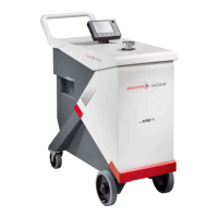
Switch set point function
The Switch set point function is used to store 2 reject points and then assign one to the hard vacuum
test or sniffer reject point (depending on the test method set).
►
Allocate a function key to [SWITCH SETPOINT] (see “Function keys”).
Settings menu
56/108