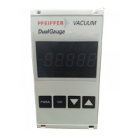
Connection selection at the electronic drive unit
The interface configuration for an electronic drive unit determines the connection
options for the DCU.
●
Connection to an electronic drive unit with multi-function connector via connec-
tion cable or via adapter from the Pfeiffer Vacuum accessories
●
Connection to an electronic drive unit directly at an available RS-485 interface
4.3.2 Earthing the device
●
The ground terminal is obligatory for DCUs with integrated power supply pack.
●
Pfeiffer Vacuum recommends connecting a suitable grounding cable to the DCU 002 to discharge
applicative interferences.
●
Alternatively, the DCU 002 is grounded following installation in a rack.
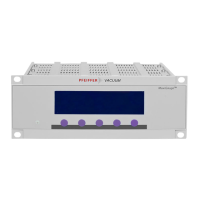
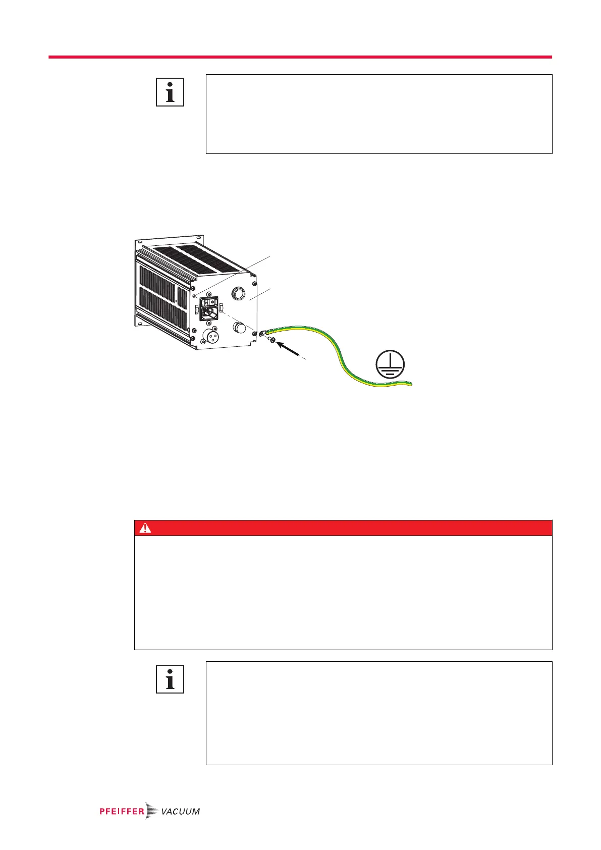
Fig. 7: Connection of the grounding cable to the DCU with integrated power supply pack
1 Ground terminal 2 Rear of housing
Procedure for DCU with integrated power supply pack
1.
Use the ground terminal at the back of the device (M4 female thread).
2.
Route the connection in accordance with locally applicable provisions.
4.3.3 Connect DCU to a vacuum pump
DANGER
Danger to life from electric shock
Power supply packs that are not specified or are not approved will lead to severest injuries up to
death.
►
Make sure that the power supply pack meets the requirements for double isolation between
mains input voltage and output voltage, in accordance with IEC 61010 and IEC 60950.
►
Make sure that the power supply pack meets the requirements in accordance with IEC 61010
and IEC 60950.
►
Where possible, use original power supply packs or only power supply packs that correspond
with the applicable safety regulations.
Observe the supreme operating control for the electronic drive unit interfaces
DIL switches in the connecting cable or bridges in the mating connector for the D-
Sub connector for the electronic drive unit enable operation of the pump without
control unit. This may cause priority conflicts with the RS-485 interface.
●
Disconnect the mating connector from the "remote" connection prior to con-
necting a DCU to electronic drive unit TC 400, TC 1200 or TM 700.
●
Switch off the supreme operating control (DIL switch S1/S2 = OFF) prior to
connecting a DCU to the electronic drive unit TC 110
Installation
20/38