6 Operation
6.1 LC-display
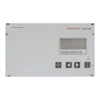
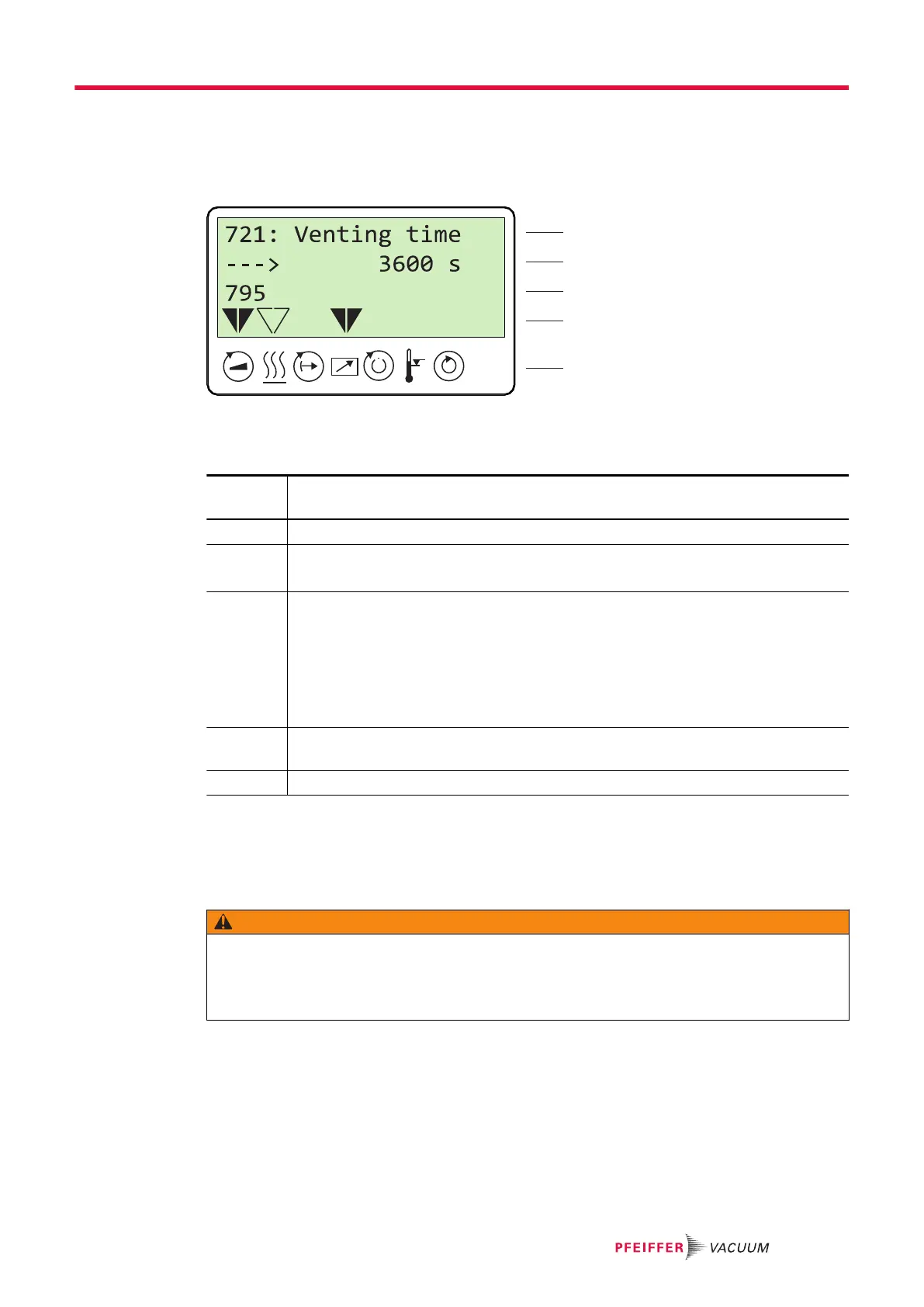
Fig. 10: LC-display, overview
The 4-line LC-display visualizes the functions of the DCU.
Line
number
Function
Line 1 Number and name of the selected parameter (e.g. 721: Vent time).
Line 2 Relevant value for the selected parameter. The arrow –––► indicates Edit
mode.
Line 3 has 2 functions:
●
Function 1: displays current messages, as well as messages pertaining to operation
and control.
●
Function 2: presentation of a required second parameter in the format [Parameter
number: value]. The function for this line can be set via parameter [P:795] Service-
lin in Line 1. All parameters can be accessed with "Servicelin". Error messages will
be displayed independently of the selected function.
Line 4 Presentation of the current equipment status with arrows which indicate the associated
symbols.
Line 5 Symbols (see below)
Tbl. 11: Meaning of functions and layout of the LC-display
6.2 Switching on the DCU
WARNING
Danger to life from electric shock in the event of a fault
In the event of a fault, devices connected to the mains may be live. There is a danger to life from
electric shock when making contact with live components.
►
Always keep the mains connection freely accessible so you can disconnect it at any time.
Switching on the current supply at the DCU with integrated power supply pack
►
Switch on the current supply with the S1 switch on the DCU.
Switching on the current supply at the DCU 002
►
Switch on the current supply via the voltage supply for the vacuum pump.
The DCU carries out a self-test and a check of the connected units after switch-on. The duration of the
self-test is indicated by a progress bar in the display, and takes around 20 seconds.
Operation
25/38