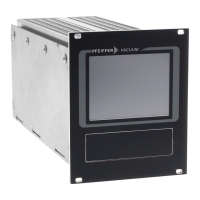
Fig. 8: Example: Connection of a DCU 002 to a vacuum pump
1 DCU 002 4 Turbopump HiPace 80
2 Interface cable M12 5 Connecting plug to power supply pack
3 Electronic drive unit TC 110
Connecting the DCU 002
The DCU 002 receives the supply voltage via the electronic drive unit interface. The RS485 serial inter-
face of the DCU is used exclusively to control the electronic drive unit of a vacuum pump. The interface
protocol us described in the operating manual of the respective electronic drive unit.
1.
Connect the "RS-485" DCU connection with the electronic drive unit of the vacuum pump.
2.
Use the interface cable M12 from the shipment.
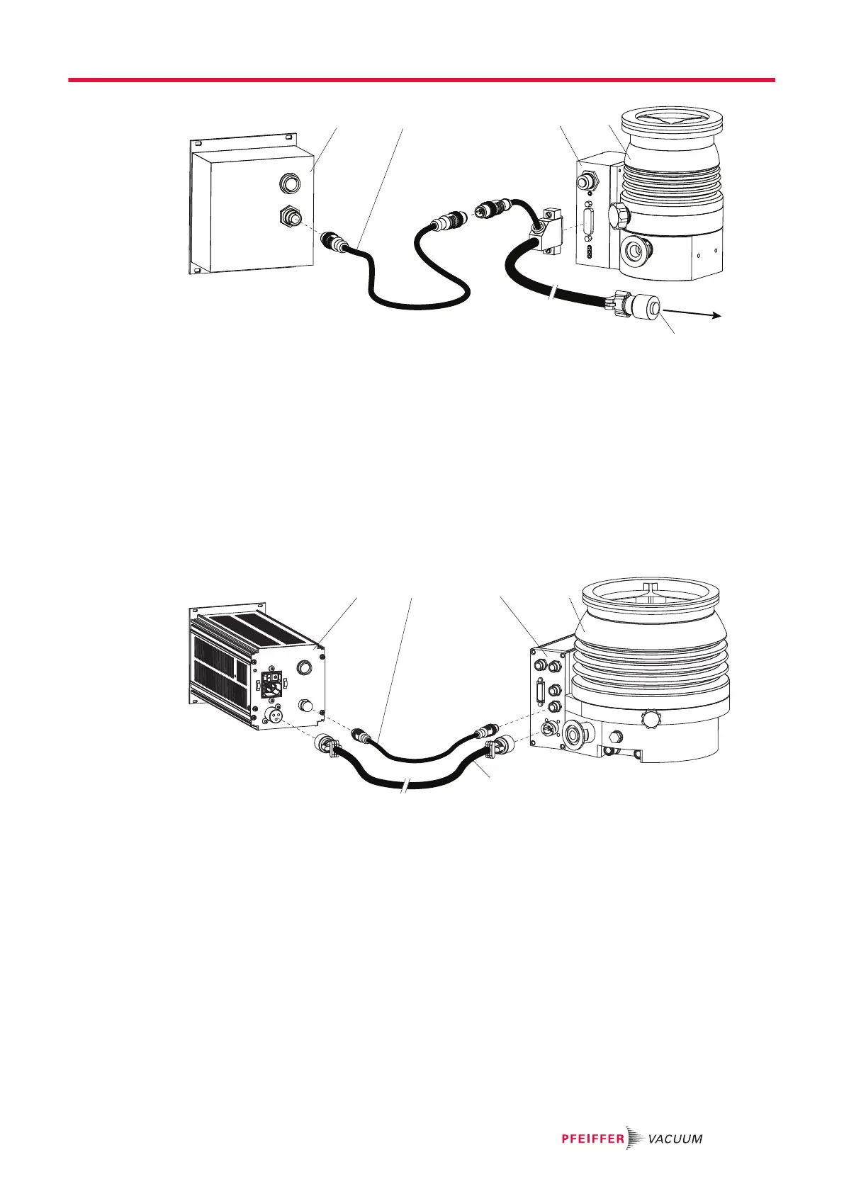
Fig. 9: Example: Connection of a DCU with integrated power supply pack to a vacuum pump
1 DCU 002 4 Turbopump HiPace 700
2 RS-485 interface cable (M12) 5 Supply voltage cable "DC"
3 Electronic drive unit TC 400
Connecting a DCU with integrated power supply pack
1.
Make sure that the power supply pack main switch is off prior to connection.
2.
Always ensure a secure connection to the earthed conductor (PE), protection class I.
3.
Connect the "RS-485" DCU connection with the electronic drive unit of the vacuum pump.
4.
Use the interface cable M12 from the shipment.
5.
Connect the "DC out" connection of the DCU with the electronic drive unit of the vacuum pump as
prescribed in the wiring diagram, or with a cable from the Pfeiffer Vacuum accessories.
Installation
21/38