PG DRIVES TECHNOLOGY NEWVSI TECHNICAL MANUAL – OPERATION
SK80151-1 15
Below is a list of self-help actions. Try to use this list before you contact your service agent. Go to the number in the list which
matches the number of flashes of the battery gauge and follow the instructions.
If the problem persists after you made the checks described above contact your service agent.
If the programmable parameter, Motor Swap has been enabled, then left and right hand
references in this table will need transposing.
1 Flash - The battery needs charging or there is a bad connection to the battery. Check the connections to the battery. If the
connections are good, try charging the battery.
2 Flashes - The left hand motor has a bad connection. Check the connections to the left hand motor.
3 Flashes - The left hand motor has a short circuit to a battery connection. Contact your service agent.
4 Flashes - The right hand motor has a bad connection. Check the connections to the right hand motor.
5 Flashes - The right hand motor has a short circuit to a battery connection. Contact your service agent.
7 Flashes - A joystick fault is indicated. Make sure that the joystick is in the center position before switching on the controller.
8 Flashes - A controller fault is indicated. Make sure that all connections are secure.
9 Flashes - The parking brakes have a bad connection. Check the parking brake and motor connections. Make sure the
controller connections are secure.
10 Flashes - An excessive voltage has been applied to the controller. This is usually caused by a poor battery connection.
Check the battery connections.
8.6 Slow or sluggish movement
If the wheelchair does not travel at full speed or does not respond quickly enough, and the battery condition is good, check the
maximum speed setting. If adjusting the speed setting does not remedy the problem then there may be a non-hazardous fault.
Contact your service agent
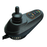
8.7 Maximum Speed / Profile Indicator is Steady
The display will vary slightly depending on whether the controller is programmed to operate with drive profiles. For more
information on drive profiles, refer to Chapter 3.
8.7.1 Maximum Speed Indication
The number of LEDs illuminated shows the maximum speed setting. For example, if the setting is speed level 4, then the four left
hand LEDs will be illuminated.
8.7.2 Profile Indication
The LED illuminated shows the selected drive profile. For example, if drive profile 4 is selected, the fourth LED from the left will be
illuminated.
8.8 Maximum Speed / Profile Indicator Ripples Up and Down
This indicates the controller is locked, refer to section 3.2 for details of how to unlock the controller.
 Loading...