NEWVSI TECHNICAL MANUAL – INSTALLATION PG DRIVES TECHNOLOGY
26 SK80151-1
The chair manufacturer is responsible for establishing the suitability of the particular wiring
arrangements used on the wheelchair for both normal use and stalled conditions. PGDT can make
general recommendations for wiring for newVSI controllers, but PGDT accepts no responsibility
for, and accepts no liability for losses of any kind arising from, the actual wiring arrangement
used.
The chair manufacturer is responsible for ensuring that only the mating connectors specified by
PGDT on the controller’s specific data sheet are used to connect to the controller. PGDT accepts
no liability for losses of any kind arising from failure to comply with this condition.
The chair manufacturer is responsible for ensuring that suitable connectors are used and securely
mated throughout the chair wiring system and that the workmanship associated with the wiring
system is of a high enough quality. Failure to meet this condition could result in intermittent
operation, sudden stopping or veering, or even create a burn or fire hazard. PGDT accepts no
liability for losses of any kind arising from failure to comply with this condition.
4.2 Wire Gauge and Types
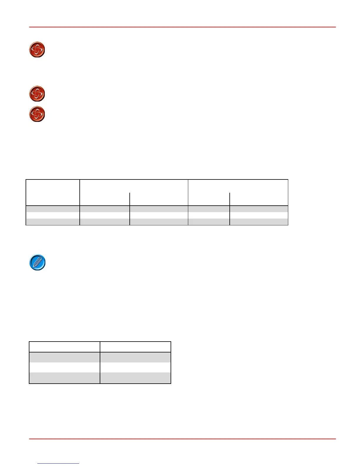
The table below gives the minimum recommended wire sizes defined in ISO7176: 2008.
For Length
<1000mm
For length
1000mm - 1500mm
For Length
<1000mm
For length
1000mm - 1500mm
30 2.5 3.0 2.5 2.5
40 3.0 4.0 2.5 3.0
50 4.0 5.0 3.0 4.0
Manufacturers must confirm these recommendations by carrying out suitable tests in particular the total length of cable used in
wiring the wheelchairs’ motors and batteries.
Battery and motor wires should use Tri-rated PVC equipment wire rated at 105°C.
4.3 Battery Wiring
The controller incorporates sophisticated current limiting circuitry as protection for the circuits in the controller.
ISO 7176-14 requires you to provide protection against short circuits in the battery wiring and the power loom in the extremely
unlikely event of a short circuit in the controller.
Place a suitable circuit breaker in series with the battery supply (refer to sections 3.1 + 3.2), for example in the link between two
batteries. If your batteries are held in separate enclosures, you must provide a circuit breaker with each of them.
The table below gives the minimum recommended circuit breaker sizes defined in ISO7176: 2008
 Loading...