Manufactured under license from Dolby
symbol are trademarks of Dolb
The following symbols appear in some headings in this manual.
: Description refers to video cassette tapes.
Description refers to DVD-VIDEO.
: Description refers to audio CD.
stem installer:
• This reminder is provided to call the CATV system installer’s attention
to Article 820-40 of the NEC that provides guidelines for prope
grounding and, in particular, specifies that the cable ground should be
connected to the grounding system of the building, as close to the point
of cable entry as practical.
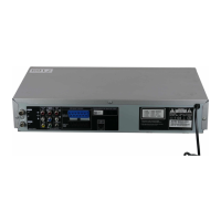
DIGITAL
AUDIO OUT
COAXIAL
AUDIO
OUT
DVD VCR
DVD/VCR
S-VIDEO
OUT
COMPONENT
VIDEO OUT
AUDIO IN
VIDEO IN
AUDIO OUT
VIDEO OUT
L
LY
R
L
R
R
C
B
/
P
B
C
R
/
P
R
DVD/VCR
AUDIO OUT
VIDEO OUT
L
R
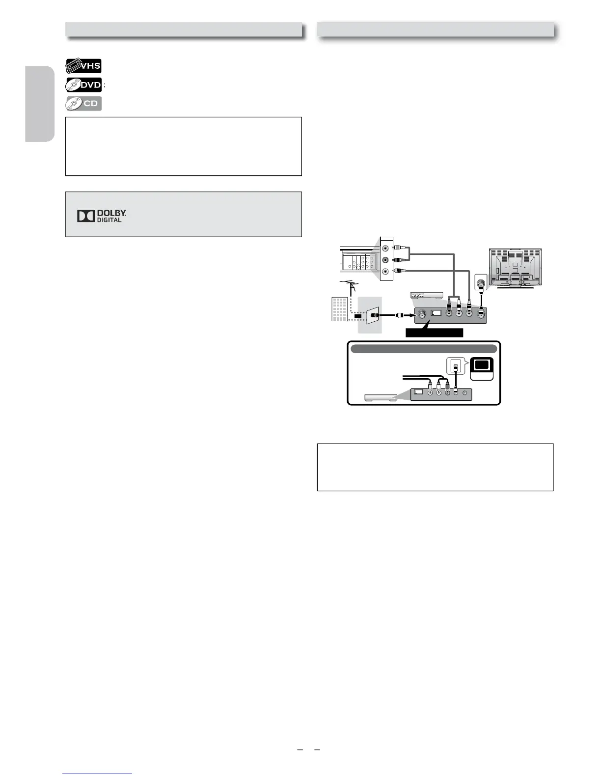
If your TV only has an Antenna input
(no A/ V inputs), you will need an
RF modulator (NOT INCLUDED) to
connect this Unit
to your TV.
RF modulator
AUDIO IN
RL
VIDEO IN
CHANNEL
43
TO TV
TV
ANT. IN
ANT. IN
No Antenna (RF) Output!
rear of TV
rear of your RF
modulator
AUDIO IN TO TVANT. IN
LR
CHANNEL
43
VIDEO IN
ANT. IN
Set channel 3 or 4
rear of this Unit
RF coaxial cable
RF coaxial
cable
VHF / UHF
antenna
cable TV
company
or
RCA video cable
RCA audio cable
If your TV has antenna in jack onl
follow the instructions below.
1)
Disconnect the power cords of the Unit from the AC
out
our RF modulator’s channel 3/4 switch to
either 3 or 4
our area. If your RF modulator has a modulator/antenna
switc
ator.
4) Plug in the power cords of the Unit to the AC outlet.
ou set the RF modulator’s channel 3/4 switch to
For more details, follow the manual supplied with the RF
mo
y.
• The picture quality may suffer if this Unit is connected through