POWER MODULE PWR207
(75W Single / Twin Subwoofer)
TABLE OF CONTENTS
Class-D Amplifier circuit description ................................................. 8-1
Exploded view + mechanical parts ................................................... 8-2
SW-out (SPK II) Boards - Circuit & Layouts ..................................... 8-3
Speaker (SPK I) Boards - Circuit diagram ........................................ 8-4
Speaker (SPK I) Boards - Component & Chips layouts ...................8-5
Mains & ECO Stby Board - Circuit diagram ...................................... 8-6
Mains & ECO Stby Board - Component & Chip layouts ................... 8-7
Mains & ECO Stby Board - Chip layout Part A ................................. 8-8
Mains & ECO Stby Board - Chip layout Part B ................................. 8-9
Supply Board - Circuit diagram ....................................................... 8-10
Supply Board - Component & Chip layouts .................................... 8-11
Supply Board - Chip layout Part A ..................................................8-12
Supply Board - Chip layout Part B ..................................................8-13
Amplifier Board - Clock Generator & connector - circuit ................8-14
Amplifier Board - Amplifier circuit .................................................... 8-15
Amplifier Board - Bottom view .........................................................8-16
Amplifier Board - Top view ..............................................................8-17
Amplifier Board - Bottom view Part A .............................................. 8-18
Amplifier Board - Bottom view Part B ............................................. 8-19
Amplifier Board - Top view Part C ................................................... 8-20
Amplifier Board - Top view Part D ................................................... 8-21
Electrical parts list - Mains, Supply, Speaker & SW-out ................. 8-22
Electrical parts list - Amplifier board ...............................................8-23
8-1
8-1
6-channel class-D amplifier
Basic operation of a class-D amplifier
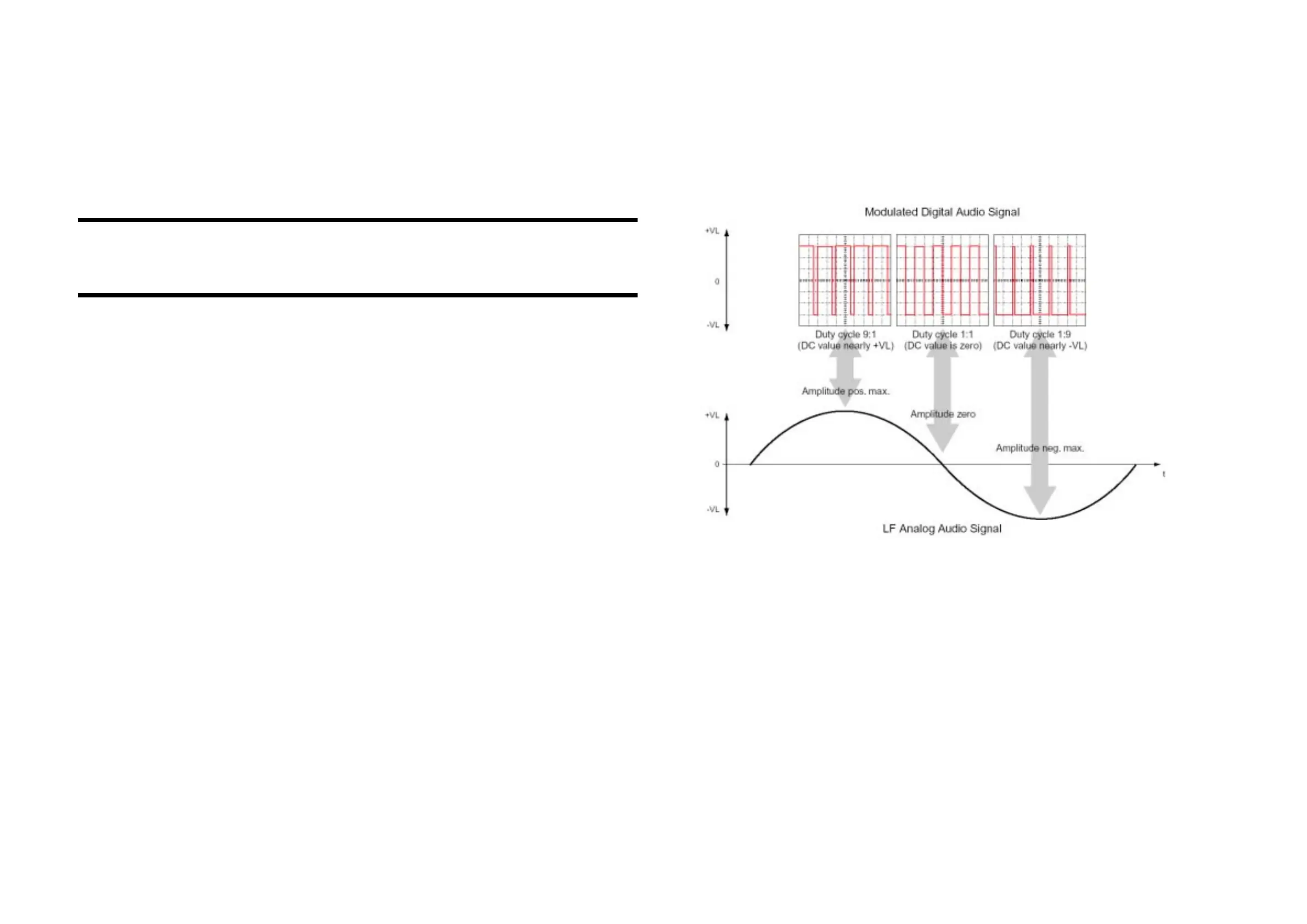
Basically, the output stage of a class-D amplifier outputs a continuous square wave swinging between positive and negative power supplies
with a fixed frequency (“clock” frequency) far beyond the audible range. The duty cycle of this square wave is modulated with the audio signal.
The output is followed by a low-pass filter which eliminates the clock frequency and allows only the audio signal going to the speaker. See
simplified drawing below.
Compared to a conventional power amplifier the benefits of the Class-D amplifier are:
• higher effiency
• lower power dissipation
• smaller heatsink required
• smaller mains transformer required
The main disadvantage of this concept is:
• The amplifier is operating with a high-frequency square wave at high amplitude and currents. This requires special precautions to prevent
excessive electromagnetic ratiation (EMC).