4 CONVERTER CHECKS (EQ FRONTAL AND E2Q REAR)
4.1 VISUAL CONVERTER CHECK
▪ Check the converter visually.
The entire converter chassis must be replaced if cracks are visible at the white IGBT body
(looking through the converter cage grid) or if the kV-power PCB Q100 is bent towards the cover plate.
4.2 MEASURING OF CONVERTER PARTS
Use an ohmmeter that has a diode test feature.
▪ Check the polarity of the meter (for ohm and diode testing):
Anode of diode symbol on meter = positive voltage >> PLUS (see measurement)
Cathode of diode symbol on meter = negative voltage >> MINUS (tables)
Ω = Normal ohm measurements
➜ = Diode test option of meter
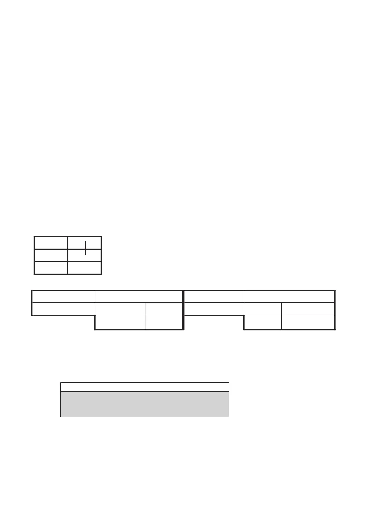
4.2.1 Rectifier check
▪ Open the right side of the converter(s) to get access to the mains rectifier.
L1
□ □
–
L2
□ □
–
L3
□
□
+
Rectifier EQV5 layout
MINUS PLUS
→
PLUS MINUS
→
L1 / L2 / L3
□ □
–
□
+ L1 / L2 / L3
□ □
–
□
+
450mV ±10%
∞ ∞
450mV ±10%
(Fig. 1)
▪ Record the conditions in the checklist (last pages).
4.2.2
IGBT check
Legend
Typical values when part is OK
Typical values of defective parts
If at least one test fails, the converter must be exchanged.
Proceed with chapter 5.
The table below shows results of IGBT emitter - collector measurement.
Converter working OK and completely assembled.
Q100 kV-power PCB 4512 108 0862x / 0934x
Converter test kit OPTIMUS for OPTIMUS 50/65/80 gen‐
erators release 3.x with converters 4512 104 7231x
Conv test Optimus CSIP Level 1 (08.0)
© 2008 Koninklijke Philips Electronics N.V.
ALL RIGHTS RESERVED
11