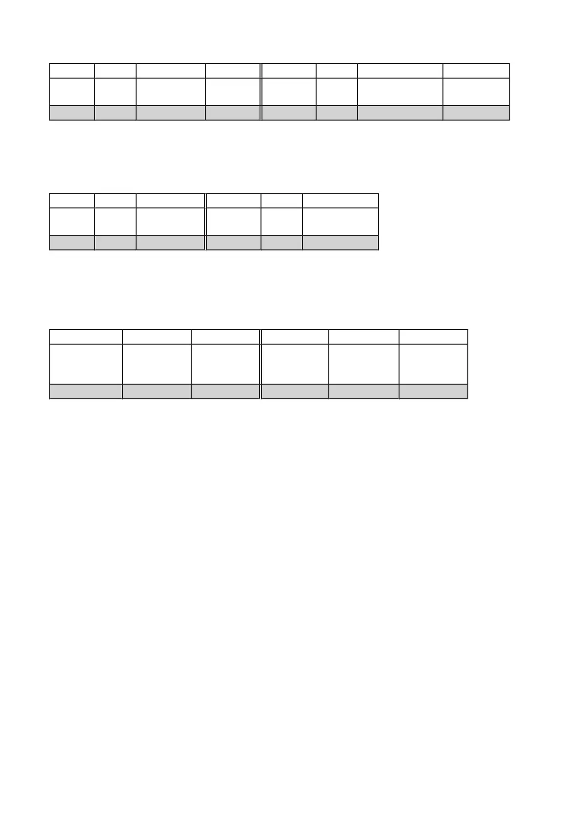
MINUS PLUS Ω ➜ PLUS MINUS Ω ➜
E1
E2,3,4
C1
C2,3,4
21.5 - 22kΩ ∞ E1
E2,3,4
C1
C2,3,4
16.5kΩ ±10% 300mV ±10%
Ex Cx 0Ω < 200mV Ex Cx 0Ω < 200mV
The table below shows values of IGBT gate - emitter resistances.
Converter working OK and completely assembled.
Q100 kV-power PCB 4512 108 0862x / 0934x
MINUS PLUS Ω PLUS MINUS Ω
G1
G2,3,4
E1
E2,3,4
3.8kΩ ±10% G1
G2,3,4
E1
E2,3,4
4.2kΩ ±10%
Gx Ex 0Ω Gx Ex 0Ω
▪ Record the conditions in the checklist (last pages).
4.2.3 Overvoltage diode check
Cathode = heat sink plate
MINUS PLUS ➜ PLUS MINUS ➜
Cathode
V500
V501,2,3
Anode
V500
V501,2,3
310mV ±10% Cathode
V500
V501,2,3
Anode
V500
V501,2,3
∞
Cathode V5xx Anode V5xx 0 Cathode V5xx Anode V5xx 0
▪ Record the conditions in the check list (last pages).
4.2.4 Resistor check (PCB versions 4512 108 0862x / 0934x)
▪ Check 2 groups of 3 parallel resistors:
R506 / 507 / 508
and
R509 / 510 / 511
With 39Ω ±5% per group. Each resistor must have a resistance of 13Ω ±5%.
▪ Record the conditions in the checklist (last pages).
Converter test kit OPTIMUS for OPTIMUS 50/65/80 gen‐
erators release 3.x with converters 4512 104 7231x
12 CSIP Level 1 (08.0)
© 2008 Koninklijke Philips Electronics N.V.
ALL RIGHTS RESERVED
Conv test Optimus