5 CHECK OF THE HIGH-VOLTAGE TRANSFORMER
▪ Remove PCB EZ130 kV-control.
▪ Insert an extender PCB at EZ130 X1 (or use the backpanel connections, which is less convenient).
▪ Establish oscilloscope connections:
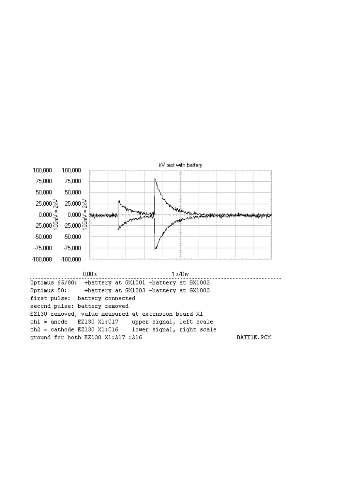
channel 1 = anode EZ130 X1:C17 10 or 20mV/div
channel 2 = cathode EZ130 X1:C16 10 or 20mV/div
ground = EZ130 X1 :A17 :A16
trigger = positive slope anode ch1 or negative slope cathode ch2
trigger level according to signal level
time base = 500ms/div or 1s/div
Signal amplitudes might look different depending on the battery type, connection cables used and the ”contact
force” at the battery.
(Fig. 3)
▪ Measure
1. with high-voltage cables and tube connected.
2. with high-voltage cables only.
3. without high-voltage cables connected.
5.1
ANALYSIS
(1) and (2) have to look almost the same (symmetry and amplitude).
When (1) has a lower amplitude or a different kV behavior compared to (2) and (3) the tube might be defective.
(3) should have a steeper (faster) discharging ramp as the capacitance of the HV cable is missing (tank only 3nF,
20m cable typically 1.5nF) assuming amplitude and symmetry are the same.
When (2) and (3) look different (amplitude and symmetry) and if (3) is symmetric the HV cable(s) might be de‐
Converter test kit OPTIMUS for OPTIMUS 50/65/80 gen‐
erators release 3.x with converters 4512 104 7231x
14 CSIP Level 1 (08.0)
© 2008 Koninklijke Philips Electronics N.V.
ALL RIGHTS RESERVED
Conv test Optimus