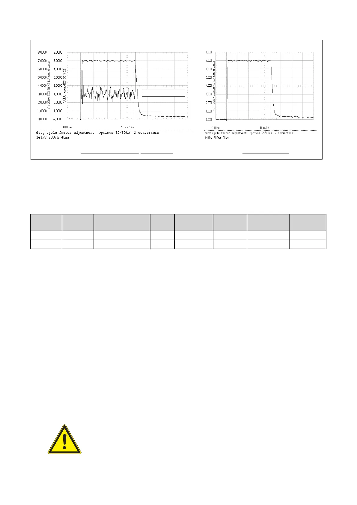
Optimus 80kW with 141kV, UCOMP = +1V AV HT with overshoot
mean value of
UCOMP
kV actual value
kV actual value +
UCOMP
(Fig. 30)
b) 125kV setting (50/65/80kW)
▪ Read the mean value of
U
COMP
for 125kV (in principle figure 29 or 30).
▪ Correct the factor duty cycle till
U
COMP
meets the required reference of 0V.
kV
setpoint
mA
setpoint
PCB type
U
COMP
Tolerance kV peak
of
AV HT
Factor duty cy‐
cle:
Date:
125kV 100mA PCB kV_control 3: +0V +1V / -0,5V 125kV
125kV 200mA PCB kV_control 4: +0V ±0.5V 125kV
Table 2: Factor duty cycle, 125kV limit
Example how to correct the factor duty cycle:
PCB kV_control 3:
▪ If the mean value of UCOMP is: > +1V increase the factor duty cycle in steps of 0.01
< -0.5V decrease the factor duty cycle in steps of 0.01
PCB kV_control 4:
▪ If the mean value of UCOMP is: > +0.5V increase the factor duty cycle in steps of 0.01
< -0.5V decrease the factor duty cycle in steps of 0.01
▪ Check also the kV peak value AV HT (not the overshoot), it must be 125kV for 125kV setpoint.
▪ Remove short link EZ130 X23 GAIN_IN.
▪ Record the results in table 2.
15.2 TUBE CONDITIONING
15.2.1 General Information
WARNING
Radiation is released during the conditioning procedure!
Converter test kit OPTIMUS for OPTIMUS 50/65/80 gen‐
erators release 3.x with converters 4512 104 7231x
Conv test Optimus CSIP Level 1 (08.0)
© 2008 Koninklijke Philips Electronics N.V.
ALL RIGHTS RESERVED
45