▪ If the UCOMP value does not match the requirements type in another factor duty cycle value,
transmit the factor by clicking on “Apply” with the left mouse button and push the active RGDV button to get
the new value validated.
▪ Switch an exposure.
The values are measured in the stationary condition. The transient behavior at the beginning of the exposure
is not taken into account.
Result: In standby the
U
COMP
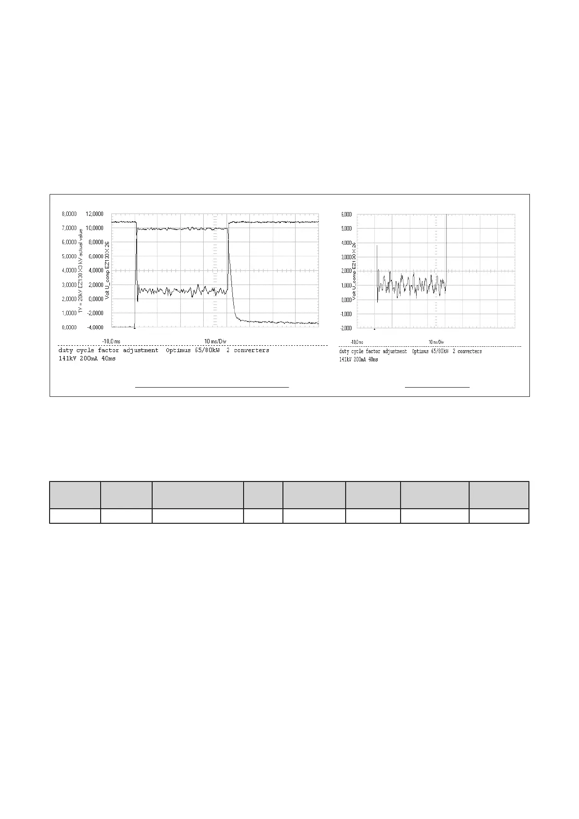
value is at about +11V, during exposure the mean value UCOMP must be as
given in table 1 or 2, refer to figure 29:
Oscillogram of a perfect alignment for 141kV UCOMP for 141kV
kV actual value +
UCOMP UCOMP
(Fig. 29)
a) 141kV setting (65/80kW only)
▪ Read the mean value of
U
COMP
for 141kV (see scope figure 29 or 30), correct the factor duty cycle till
U
COMP
meets the required reference of +1V.
kV
setpoint
mA
setpoint
PCB type
U
COMP
Tolerance kV peak
of
AV HT
Factor duty cy‐
cle:
Date
141kV 200mA PCB kV_control 4: +1V ±0.5V 138kV
Table 1: Factor duty cycle, settings 141kV (150kV limit)
Example how to correct the factor duty cycle:
PCB kV_control 4:
▪ If the mean value of
U
COMP
is: > +1.5V increase the factor duty cycle in steps of 0.01
< +0.5V decrease the factor duty cycle in steps of 0.01
▪ Check also the kV peak value AV HT (not the overshoot), it must be 138kV for 141kV setpoint
(see scope figure 30).
▪ Remove short link EZ130 X23 GAIN_IN.
▪ Record the results in table 1.
Converter test kit OPTIMUS for OPTIMUS 50/65/80 gen‐
erators release 3.x with converters 4512 104 7231x
44 CSIP Level 1 (08.0)
© 2008 Koninklijke Philips Electronics N.V.
ALL RIGHTS RESERVED
Conv test Optimus