During alignment this factor duty cycle must be entered via AGenT. The influence of this factor as a correction
value for the Z-data table is monitored as the
U
COMP
signal, since the PI-controller is deactivated by the grounded
GAIN_IN
signal.
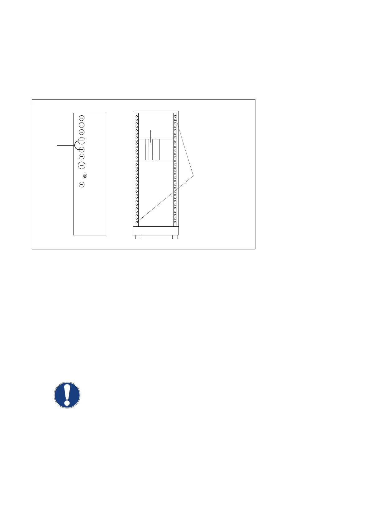
15.1.1.1 Connecting and setting the scope
For connections see figure below:
Status
EZ130
GNDA
GAIN_IN
AV CA
AV AN
AV HT
UCOMP
Generator front
EZ130 front
Osci: Y1 ==> X3
X4
X5
X6
X23
Osci: Y2 ==> X26
X32
H800
X800
Short link
Ground the probes in
one of these drilling holes
(Fig. 27)
Channel 1 = EZ130 X3 ---> AV HT ---> 20kV/V ---> 1V/div --> Zero-line at bottom of screen
Probe GND = one of the drilling holes at the front cabinet chassis
Channel 2 = EZ130 X26 ---> UCOMP ---> 1V/div ---> Zero-line 2 div from bottom of screen
Probe GND = one of the drilling holes at the front cabinet chassis
Trigger = external (preferred) ---> CTRL_X_C/ ---> backpanel EZX74 / negative slope
or = internal channel 1 ---> AV HT ---> EZ130 X3 / positive slope at +3V
Probe GND = one of the drilling holes at the front cabinet chassis
Time base = 5 or 10ms/div ---> trigger delay -1div
NOTE
A digital scope should not have any other ground connection than the ground of the
three probes at the drilling holes at the front generator chassis.
A mains-driven scope must be isolated from earth potential, otherwise it might display
artefacts.
Converter test kit OPTIMUS for OPTIMUS 50/65/80 gen‐
erators release 3.x with converters 4512 104 7231x
42 CSIP Level 1 (08.0)
© 2008 Koninklijke Philips Electronics N.V.
ALL RIGHTS RESERVED
Conv test Optimus