– the individual primary coils (anode or cathode) at a 65/80kW driven by 1 converter each
must always be the same.
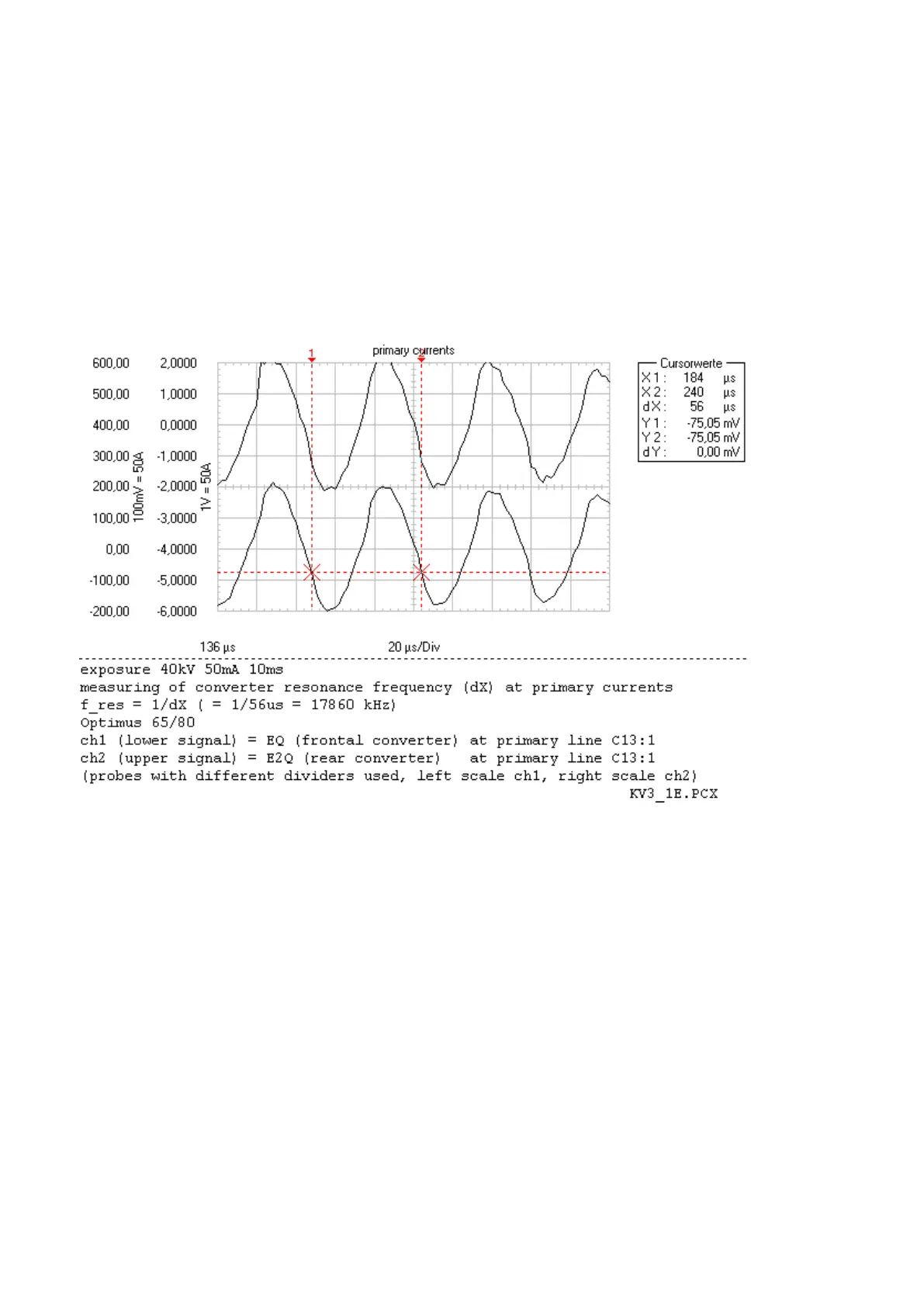
With a tolerance of 5% for the primary coil inductance and for the resonance capacitors in the converters the
resonance frequency must be within a range of 17.160kHz (1/f = 58.3µs) and 18.970kHz (1/f = 52.7µs).
Optimus 65/80 with 2 converters:
Both currents must be in phase (if not check probes at current transformer pins 1 + 2).
▪ Compare with chart.
It does not matter whether the tube is adapted or not.
(Fig. 21)
Optimus 50:
If the resonance frequency is not within the specified range the suspected part might be
– the HV transformer
– the resonance capacitor(s) of the converter.
Optimus 65/80:
Both resonance frequencies must be within the specified range. If not the suspected part might be
– the HV transformer
– the resonance capacitor(s) of the individual converter.
12.2
MEASUREMENT OF KV BEHAVIOR WITH AN ADAPTED TUBE
▪ Switch OFF the generator and wait until the converter DC is discharged.
▪ Place one oscilloscope probe at
Converter test kit OPTIMUS for OPTIMUS 50/65/80 gen‐
erators release 3.x with converters 4512 104 7231x
34 CSIP Level 1 (08.0)
© 2008 Koninklijke Philips Electronics N.V.
ALL RIGHTS RESERVED
Conv test Optimus