9 KV-DRIVER TEST
CAUTION
Before this driver test can be carried out the kV power unit(s) must be disconnected
from the mains supply (leads of unit(s) EQ/E2Q to ENK1 :1, :3, :5)
This safety measure is also valid for the chopper test
to guarantee that the measurements can be carried
out without any risks involved.
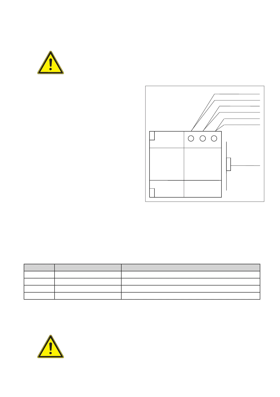
1 3 5
ENF 1 ENK 1
2Q X1103
Q X1103
2Q X1102
Q X1102
2Q X1101
Q X1101
Z X47
X1
EN100
(Fig. 5)
▪ Switch ON the generator.
Ignore error codes 02HI and 02HJ now, the DC supply is off and these errors must come up.
▪ Check whether the gate voltage is about -14.2 V ±0.3V against emitter for every IGBT.
▪ Check the ±15 V supply for the IGBT drivers. Drivers 1 and 2 are supplied by chopper 1 while drivers 3 and 4
are supplied by chopper 2. The common zero point is the emitter.
Emitter +15 V supply at heat sink -15 V at resistor
E1, X101 A100 : 3 X10²
E2, X201 A200 : 3 X202
E3, X301 A300 : 3 X302
E4, X401 A400 : 3 X402
The kV driver test is software-controlled via PC. Due to the missing PREP and exposure requests the signals
EN_X_C/ and CTRL_X_C/ have to be set low–active at the backpanel at locations X76 and X74
(see drawing Z2-5.1/2).
CAUTION
Do not forget to remove these connections after the test. Otherwise kV start immedi‐
ately with the PREP command in normal application mode.
Converter test kit OPTIMUS for OPTIMUS 50/65/80 gen‐
erators release 3.x with converters 4512 104 7231x
Conv test Optimus CSIP Level 1 (08.0)
© 2008 Koninklijke Philips Electronics N.V.
ALL RIGHTS RESERVED
19