Test of control signal(s) and driver(s) behavior:
The range of the control signal is + 3.7 V ± 0.2 V for the ON condition and + 1.2 V ± 0.2 V for the OFF condition
at the specified measuring point against generator ground (see schematic diagrams and PCB layout).
The range of the driver signal (gate against emitter) is - 14.2 V ± 0.3 V for the OFF condition and + 13.5 V ± 0.3 V
for the ON condition.
▪ Select menu ”FU_kV/ Faultfind/ Functional Test/ Test Converter” at the service PC.
The question [power supply mains - E disconnected ?:] comes up.
Answer with ”yes” (type Return twice) and transmit with [F2].
If the test takes longer than 10 minutes it may happen that the test is denied by the kV control. This happens if
the DC voltage = E–value is ≥ 5 V (the DC capacitors are slowly charged by the ±15 V of the drivers). Then short–
circuit the DC at collector C1 and emitter E2.
Do not establish a constant short–circuit to avoid problems after the test!
The test itself is short. The pulse time is 2.5 s long, but the PC screen displays [completed] after 5 s.
kV_control sends pulses for 5 s, but the hardware timer on the kV_control inhibits more pulses after 2.5 ms. Within
this time the actual kV must be on the nominal value.
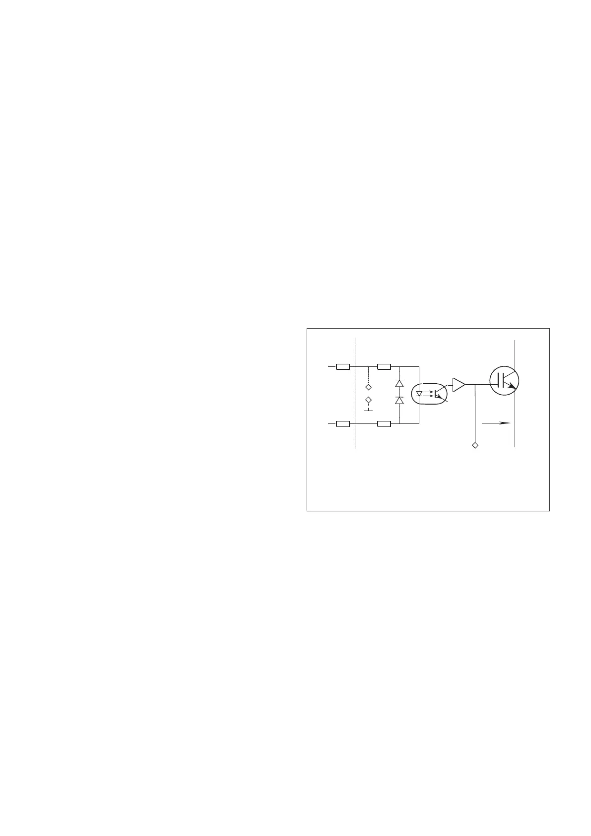
Test 1: Optical coupler / activation of the gate
Test 1: Input and output:
▪ Put a 2–beam oscilloscope to every measuring
point of the control signals (channel A) and to every
gate belonging to the inputs (channel B).
Measuring points X6...X10 are present at the
kV power unit.
▪ Trigger with the negative slope of channel A, take
10..50ms/div.
IGBT
V1...V4
emitter
on = +13.5V
off = -14.2V
gate
kV -power EQ 100
kV -control
EZ 130
off=0V
on=5V
off=5V
on=0V
R#
X#
X10
channel A: X6
X7
X8
X9
against chassis/X10
channel B: X100
X200
X300
X400
(Fig. 6)
Converter test kit OPTIMUS for OPTIMUS 50/65/80 gen‐
erators release 3.x with converters 4512 104 7231x
20 CSIP Level 1 (08.0)
© 2008 Koninklijke Philips Electronics N.V.
ALL RIGHTS RESERVED
Conv test Optimus