15 APPENDIX
15.1 ALIGNMENT OF FUNCTION UNIT KV
15.1.1 General information
The actual value of the set kV must be attained at least after 2ms. At kV rise phase there must be neither kV
break-in nor a kV overshoot.
The factor duty cycle is based on an adapted tube and determines at local mains voltage and mains resistance
conditions:
– the kV rise phase
and
– the kV behavior during the exposure in falling load technique
as it takes into account the tolerances of the following FRUs (Field Replaceable Units):
1. PCB EZ 130 **
kV_control_3 = 50kW 1 converter 4512 108 0908x / 4512 178 0026x
kV_control_4 = 65/80kW 2 converters 4512 108 0910x / 4512 178 0028x
2. A complete power converter unit Q **
kV_power PCB(s) Q100 (part of the power converter unit)
IGBT transistors (part of the power converter unit)
3. Resonance capacitors (part of the power converter unit) **
4. High-voltage transformer **
An exchange of one of the ** marked parts requires a realignment of the factor duty cycle.
The factor duty cycle is stored in the memory of PCB CU EZ139. If the CU has to be replaced the CU complete
backup can be reloaded (with the actual factor) to the NVRAM memory or the factor duty cycle must be re-aligned.
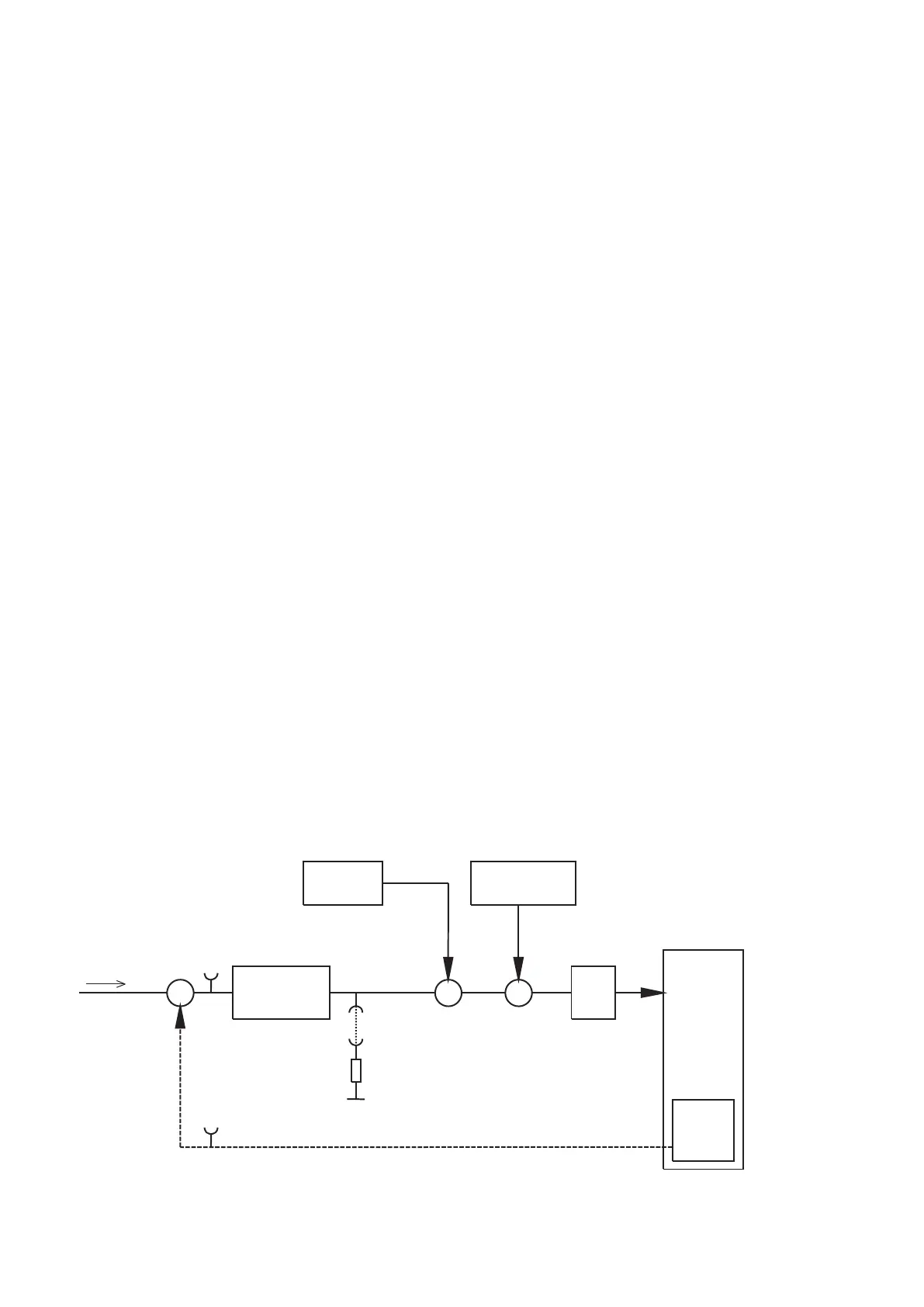
Refer to figure 26:
PI-controller
EZ130
Z-data table
+
0
CU Z139
factor duty cycle
PWM
Converter
HV
tank
+
-
X26
X3
X6
X23
UCOMP
AV HT
GAIN_IN
Ground
NV HT
(Fig. 26)
Converter test kit OPTIMUS for OPTIMUS 50/65/80 gen‐
erators release 3.x with converters 4512 104 7231x
Conv test Optimus CSIP Level 1 (08.0)
© 2008 Koninklijke Philips Electronics N.V.
ALL RIGHTS RESERVED
41