15.1.1.2 Deactivating the kV controller
▪ Connect EZ130 X23 GAIN_IN and X6 GNDA with a short link (use a short wire).
CAUTION
This alignment requires exposures with high kV.
Be sure the tube has been warmed up before.
15.1.1.3 Setting of exposure data
a) Set 141kV in case
– of 65/80kW generators
– the tube limit (of at least one tube) is 150kV, perform this adjustment at the tube which has the highest kV limit
programmed.
b) Set 125kV in case
– of 50kW generators
and
– of 65/80kW generators if the programmed application limit of the tube limit is 125kV.
NOTE
Any tube arcing during this adjustment requires the execution of the tube conditioning
next as described in Appendix (15.2.TUBE CONDITIONING).
Disconnect the short link between X23 and X6.
Start over this adjustment from chapter 15.1.1.2 onwards if the tube conditioning was
successful.
▪ Set kV and mA values according to the programmed tube limits:
a) 141kV: 200mA at kV_4 (65/80kW)
b) 125kV: 100mA at kV_3 (50kW)
200mA at kV_4 (65/80kW)
▪ Set the exposure time: 40ms
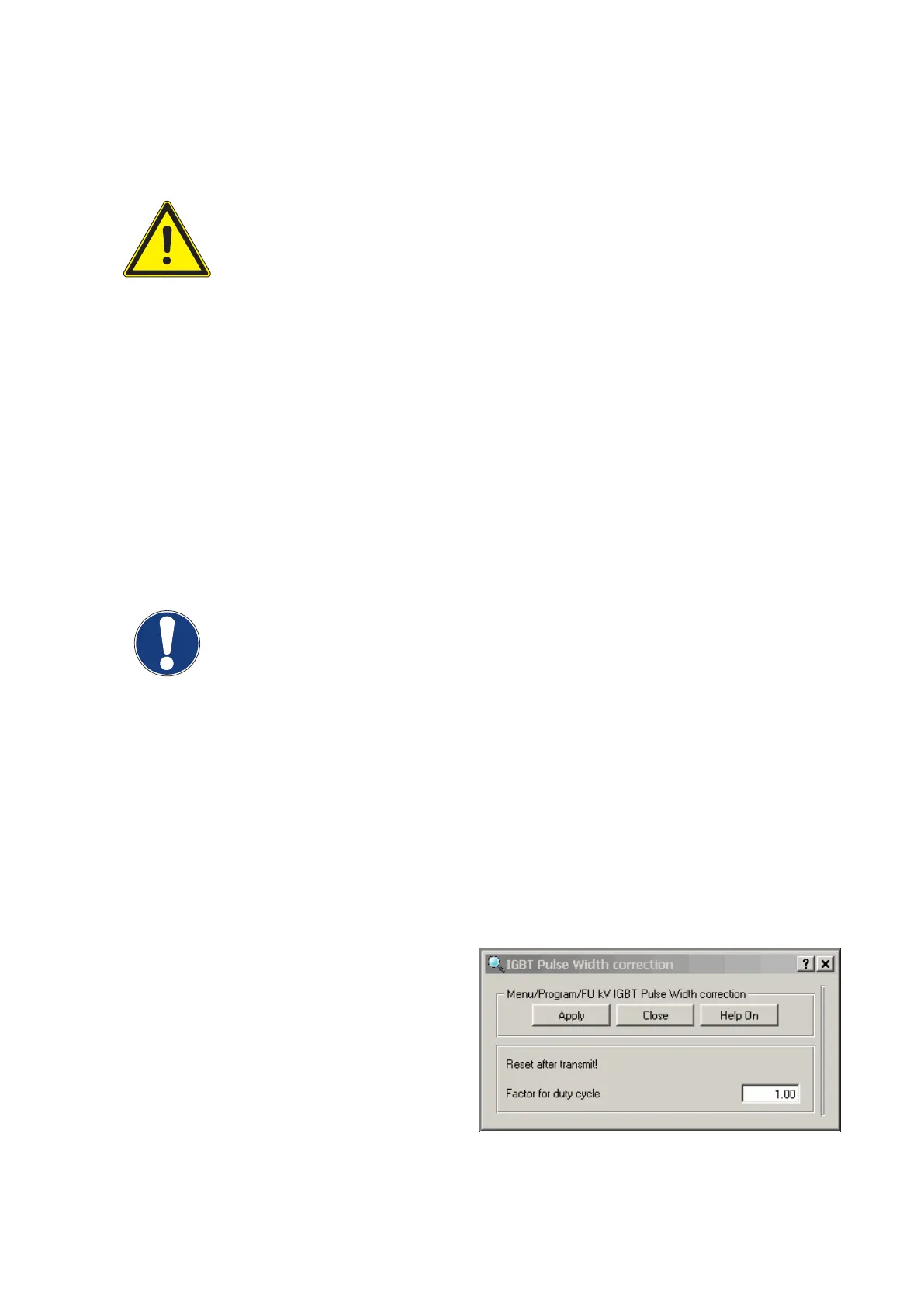
15.1.1.4 Adjustment of the factor for duty cycle
▪ Adjust the factor duty cycle via service software
AGenT by measuring UCOMP with the scope.
▪ Connect the service PC and start AGenT:
Select Menu: Program / FU kV IGBT Pulse Width
Correction
▪ Set the starting value Factor Duty Cycle to 1.00:
(Fig. 28)
Converter test kit OPTIMUS for OPTIMUS 50/65/80 gen‐
erators release 3.x with converters 4512 104 7231x
Conv test Optimus CSIP Level 1 (08.0)
© 2008 Koninklijke Philips Electronics N.V.
ALL RIGHTS RESERVED
43