3.2 System Function Blocks
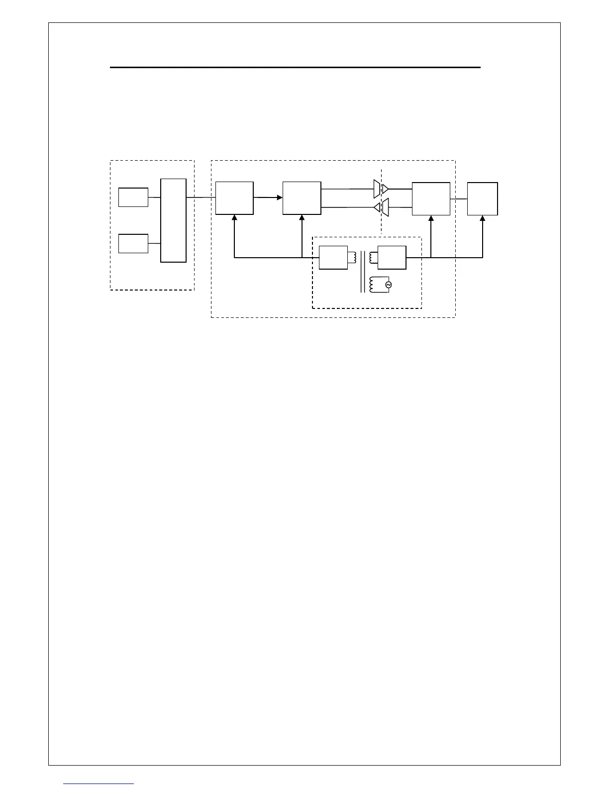
Figure 3-1 shows the main system function blocks of M3500A multimeter.
Figure 3-1
As shown in Figure 3-1, the system consists of Front/Rear Selector, Main
Board Module, and Panel Module. In this section, the discussion of the
front/rear selector is provided. The detail of the panel module is provided in
section 3.3, and the main board module is discussed in section 3.4.
The front/rear selector is used to select either the front terminals or the rear
terminals. The front terminals and the rear terminals have the same
functions and users can choose one of them for their convenience. Both front
and rear terminal have a fused current input terminal (Input-I) to protect
against potential catastrophic damage caused by accidental input
connection. The current input fuses used in M3500A is the type 3.15A, 250
V, 5
20 mm, fast acting, ceramic tube with a high breaking character
(Picotest part number: 024-001-000008, the reference number: FS101).
For more detail about current input fuses, please refer to section 2.2.
Panel
Module
System Function Blocks of M3500A
Power Supply