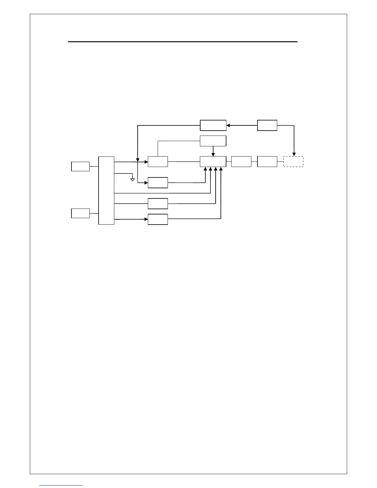
3.4.2 Analog Front-end Circuitry
The purpose of the analog front-end circuit is to converter the input signals
from the front or rear terminal to ADC (analog-to-digital converter) input.
The block diagram of the analog front-end circuit of M3500A is shown in
Figure 3-5.
Figure 3-5
The purpose of the function switching circuit is to connect the input terminal
to the various functions. All measurement signals are changed to a DC
voltage and then sent to the function switching circuit. The amplifier in the
function switching circuit converts the voltage to a properly value according
to the function which is selected and then send it to the A-to-D converter
through the PGA circuit.
The PGA circuit switches the various signals for measurement. In addition to
the input signal, it also switches among reference and zero signals at various
phases of the measurement cycle.
DC input signals from Input-HI terminal are routed via a protection circuit to
the function switching circuit. If an overload condition occurs, the protection
circuit will disconnect the analog input signal from the rest of the analog
circuit. For the 100 VDC and 1000 VDC ranges, the protection circuit is open
and input DC voltage is through a DCV divider R204 to the function switching
Analog Front-End Circuit