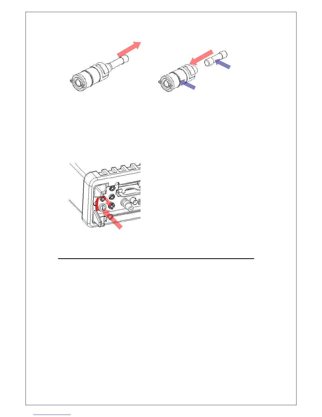
Figure 2-22
[Step 5]
Insert the fuse holder back and turn it right as shown in Figure 2-23. Make
sure the fuse holder is properly seated and secured.
Figure 2-23
2.3 Pass/Fail Output From USB Connector
The USB connector on the rear panel of M3500A is a series “B” connector.
When the USB interface is disabled (IEEE-488 interface is selected), the
internal pass and fail TTL output signals (limit testing) will be connected to
the USB connector.
The pass and fail signals are low true and indicate the Math Pass/Fail Limit
Test result for the next reading to be output to the GPIB interface. The
signals are active low for approximately 2ms (