3.4.1 Power Supply Circuitry
In this section, a basic circuit theory that can help you to troubleshoot the
power supply circuit of M3500A is provided. The power supply circuit
transforms the AC line voltage to required voltage (AC or DC) for various
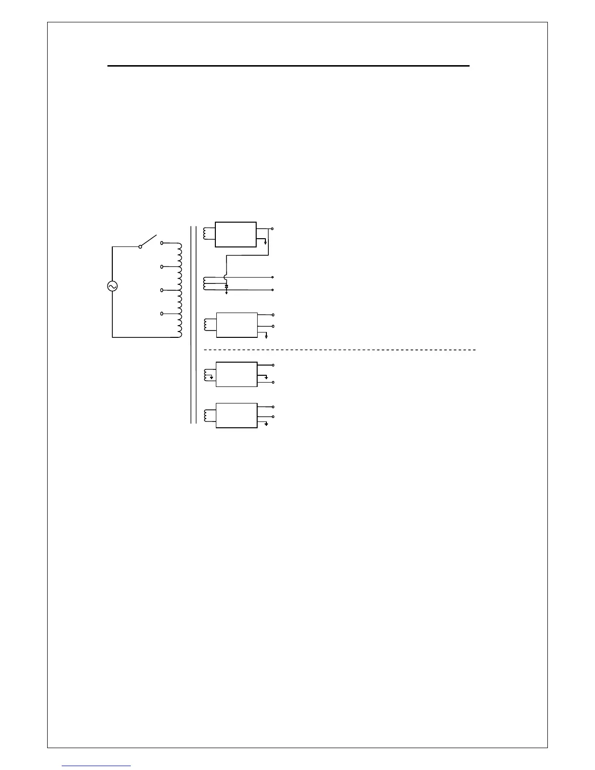
internal circuits. The block diagram of power supply circuit is shown in
Figure 3-4.
Figure 3-4
As shown in Figure 3-4, AC power is applied through the line voltage
selector to power transformer. There are four selections of line voltage (240,
220, 120, and 100 Vac) can be applied to M3500A. You must choose a
correct line voltage for your multimeter according to your local power utility
voltage or damage may occur.
The power transformer has a total five secondary windings to produce AC
and DC voltages for M3500A. AC voltage is used to provide the VFD filament
voltage, and each DC supply uses a regulator circuit for various purposes.
Please refer to Figure 3-4 to check the purpose of each supplied voltage.