circuit.
The ACI or DCI input signal is applied to the current shunt circuit from the
Input-I terminal and a relay is used to select shunts. For 10mA DC and
100mA DC ranges, a 5.1
resistance is shunted across the input. For the
other DCI and all ACI ranges, a 0.1
shunt is used. Since the shunt
resistance is known, a voltage proportional to the input current is generated
and measured by the function switching circuit.
Resistance measurements are made by applying a known current through
an unknown resistance. The current from OHMS current source makes a
voltage drop across the unknown resistance. The resulting voltage drop is
then routed through the protection circuit and measured by the function
switching circuit. For 4-wire ohms measurements, Sense-HI and Sense-LO
are connected to the function switching circuit, too.
AC input voltage from the Input-HI terminal is sent to a RMS to DC converter
via protection circuit. RMS to DC converter changes the input AC voltage to
a DC voltage and then sends it to the function switching circuit. All voltage
ranging is performed in the converter circuit so that the input of the function
switching circuit is nominally 2 VDC for a full scale AC input.
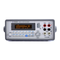
3.4.3 ADC & MCU
Figure 3-6 shows the block diagram of the A-to-D convert circuit of
M3500A.
Figure 3-6