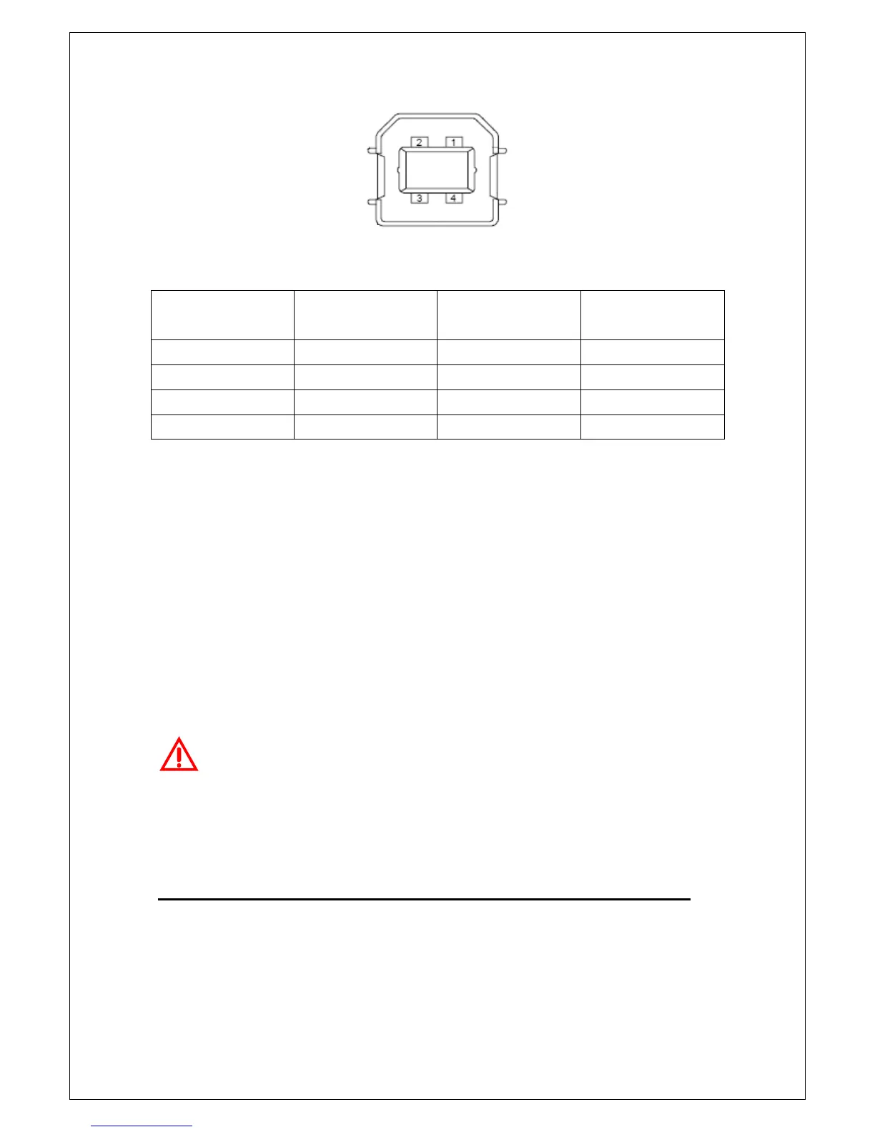
Figure 2-24
Contact
Number
Signal Name
Typical Wiring
Assignment
Description
1 VBUS Red Floating
2 D- White Limit Test Pass
3 D+ Green Limit Test Fail
4 GND Black GND
Table 2-2
If you disable the USB interface, the Pass/Fail output function will enable
automatically. Please follow the procedure below to enable/disable this
function.
Procedure: MENU
ENALBLE/DISABLE
Warning! You can’t use the USB interface if you want to enable the
Pass/Fail signal output. You must use the GPIB interface for remote control.
Please disconnect the USB cable from you multimeter. The signal from the
USB cable may make the Pass/Fail signal output abnormal.
2.4 MCUs & DSP Firmware Upgrade
M3500A has three microprocessors, DSP processor, Panel processor, and
Front-end processor, for various internal systems. PICOTEST allows users to