The analog-to-digital converter (ADC) is used to change dc voltage into
digital information. The digital signals are then sent to the main controller on
the main board module through opto-couplers to calculate readings. The
voltage reference circuit is used to provide precision voltage reference for
the multimeter.
A microprocessor (front-end processor), U2001, controls the functions of
ADC and the analog front-end circuit to make sure the analog-to-digital
conversions are performed properly. The output data of the ADC circuit are
then sent to the main controller on the main board module through the Tx
lines via opto-couplers.
When the multimeter is triggered, an analog-to-digital conversion is
performed. The ADC starts by clearing the integrator slope count in the
front-end MCU, and the slope count is latched at the end of the integration
period. The slope count provides the most significant bits of the input
voltage conversion.
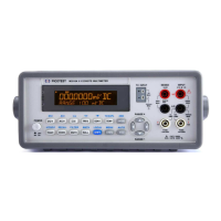
3.4.4 Main Control Circuitry
The main control circuit controls operations of the entire instrument. Figure
3-7 shows the block diagram of the main control circuit.
Figure 3-7