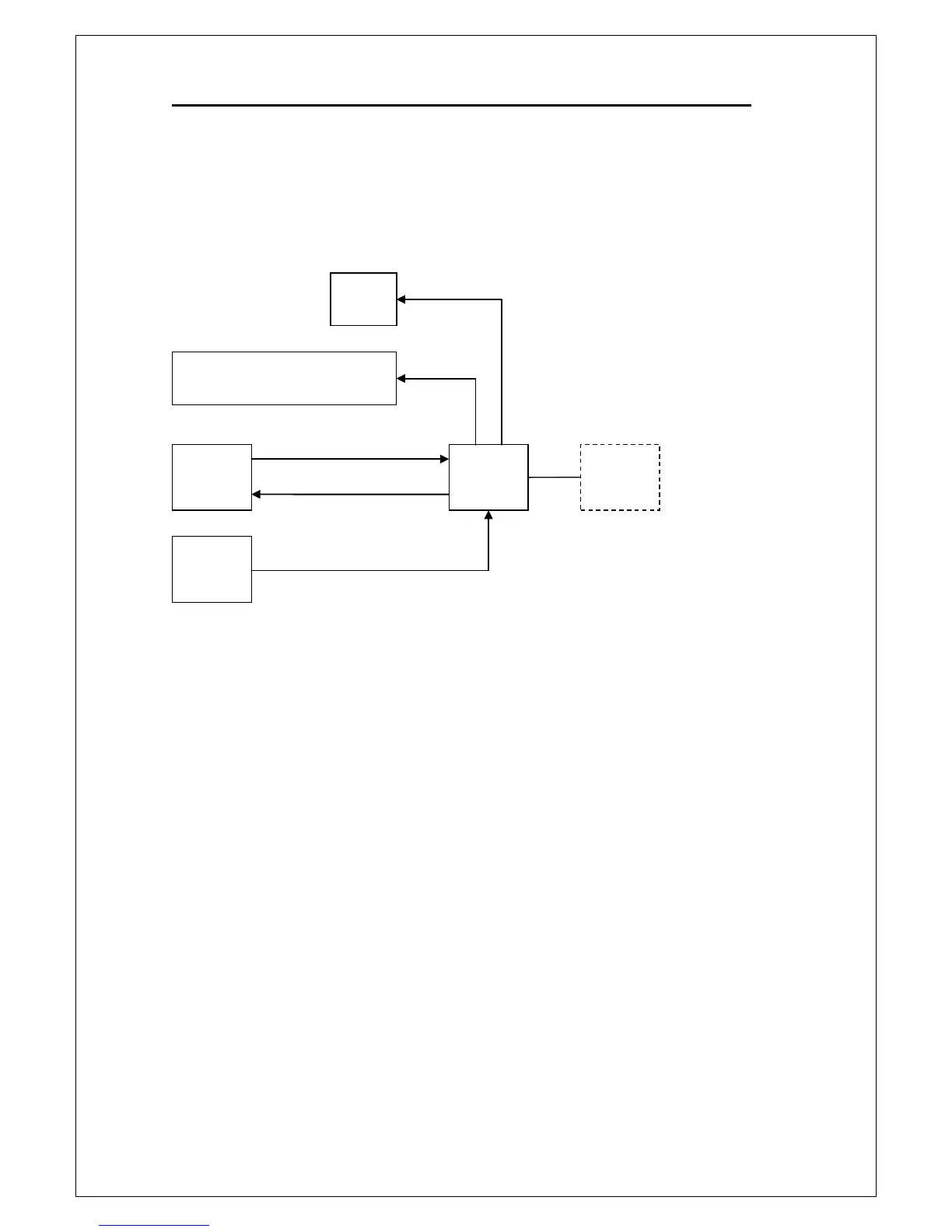
3.3 Panel Module
The panel module consists of VFD control, keypad scanning, and beeper
control. Figure 3-2 shows the block diagram of the panel module of
M3500A.
Figure 3-2
Panel MCU U3 controls the functions of panel module. Communication
between the panel module and the main board module is accomplished
through a 4-wire bidirectional serial interface. The panel MCU sends a key
scanning signal sequentially to the keypad via scan lines to detect the status
of keys. In a similar manner, the key data are sent back sequentially through
data lines.
If any key is pressed, a key down parameter will be sent to panel MCU. Panel
MCU U3 interprets the key down data and sends the data to the main
controller on the main board module. Main controller U1601 will operate
according to the received data, and then return the result to U3. According
to the result from U1601, U3 sends control signals to the VFD (vacuum
fluorescent display) for correct display and to beeper to generate a beep.
Filament voltage for the VFD is derived from the power supply transformer.
A 50Hz/60Hz detecting circuit consists of comparator U4 detects the