12 Captain-i - Installation Guide
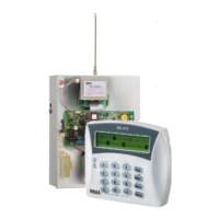
3.1.4 Arming with key/Remote control
Connect the key or relay output of the remote control receiver to Zone 6 and GND.
Zone 6 must be programmed as normally open and as Key input (see section 5.4.4).
For better protection it is recommended to connect a 10KΩ EOL resistor. The key can
be of momentary or latch position type (see section 5.4.4).
GND
Electrical Diagram
N.O. connection
Without EOL
resistor
N.C. connection
R2
Key wiring
Notes:
When using EOL resistors, the input must be programmed accordingly (see section
5.1.2).
The key for the properties of Zone 6 may be set as either N.O. or N.C.
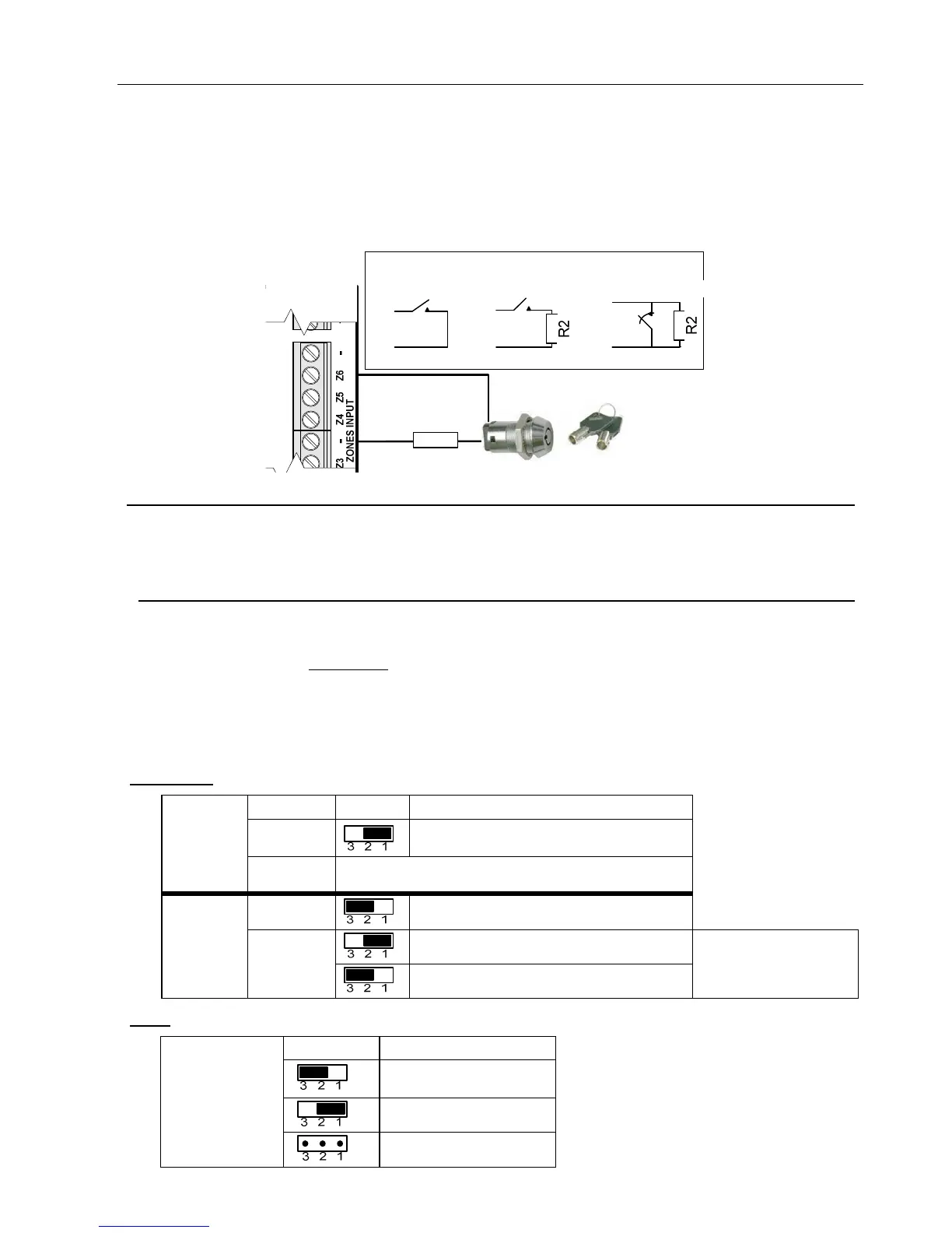
3.1.5 Sirens & Jumpers
3.1.5.1 Jumpers
♦ JP1: Sets whether the output, when triggered, is switched to (V+) or (GND)
♦ JP2: Sets whether the power source is stabilized or unregulated
♦ JP3: Is set according to the EOL values
JP 1 & 2:
Jumper Pins Connection
JP1
Is switched to GND (-) (default)
Horn
siren
JP2 Has no effect (is bypassed)
JP1
Is switched to positive (+)
Stabilized up to 13.8V (default)
DC
siren
JP2
Unregulated up to 20V
Protected with
0.9A thermal
fuse
JP3:
Pins Values
10k, 13k (default)
10k, 10k
Connected
EOLs
5.1k, 6.8k
 Loading...


