PDP-6071PU
132
1234
1234
C
D
F
A
B
E
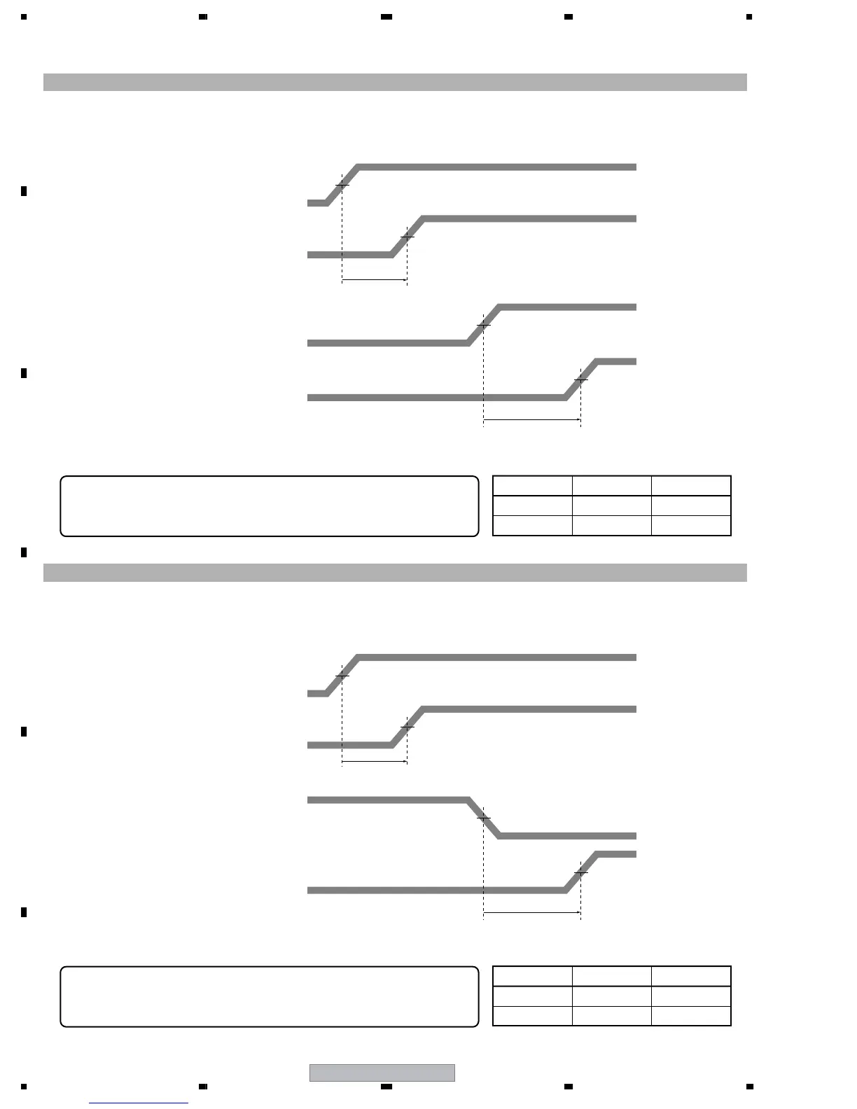
1 Measure the delay time for the SUS-U signal.
2 Check the delay time for the SUS-B signal.
Adjust the variable control so that the SUS-B delay time becomes "SUS-U delay time + α ± 5 nsec."
Note: For details on measuring points of waveform, see the figure below.
1.5 V
1.5 V
5 V
SUS-B delay time: ∆ Tsus-b
Adjust so that "∆ Tsus-b = ∆ Tsus-u + α ± 5 nsec," using the variable
controls shown in the table below:
SUS-U signal (input to the DRIVE Assy)
Value of α
SUS-U signal (input to the DK module)
SUS-B signal (input to the DRIVE Assy)
SUS-B signal (input to the MSK module)
5 V
SUS-U delay time
∆ Tsus-u
SUS-B delay time
∆ Tsus-b
Assy VR Time
X DRIVE VR1002 70 nsec
Y DRIVE VR2010 85 nsec
DELAY ADJUSTMENT OF THE CONTROL SIGNAL (SUS-B)
1 Measure the delay time for the SUS-D signal.
2 Check the delay time for the SUS-G signal.
Adjust the variable control so that the SUS-G delay time becomes "SUS-D delay time + β ± 5 nsec."
Note: For details on measuring points of waveform, see the figure below.
1.5 V
1.5 V
5 V
SUS-G delay time: ∆ Tsus-g
Adjust so that "∆ Tsus-g = ∆ Tsus-d + β ± 5 nsec," using the variable
controls shown in the table below:
SUS-D signal (input to the DRIVE Assy)
Value of β
SUS-D signal (input to the DK module)
SUS-G signal (input to the DRIVE Assy)
SUS-G signal (input to the MSK module)
5 V
SUS-D delay time
∆ Tsus-d
SUS-G delay time
∆ Tsus-g
Assy VR Time
X DRIVE VR1001 120 nsec
Y DRIVE VR2011 100 nsec
DELAY ADJUSTMENT OF THE CONTROL SIGNAL (SUS-G)
 Loading...