[MSG] [3]
CAMMOTOR
select
[4]
ELVMOTOR
select
[5]
LOADMOTOR
select
[3]
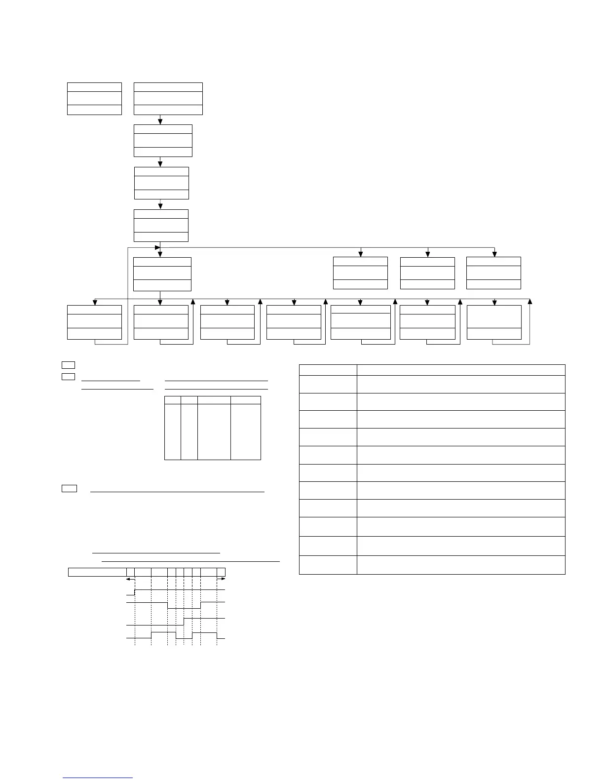
Mechanism Test In
Initial State
[MSG]
CD Test Mode
[TYPE]
New Test Mode
Source CD
Test Mode In
[6]
CAM+LOADMOTOR
select
[SEEK UP]
MOTOR FWD drive
[Key]
[MSG]
[SEEK UP]
[SEEK DOWN]
[3]
[4]
[5]
[6]
Operation
To the Mech Test initial state
Drives the motor selected by [F.7] to [F.10] in the FWD direction.
Operative only while the key is pressed.
Selects the CAM MOTOR.
[5]
CD Test Mode
[SEEK DOWN]
MOTOR REV drive
Drives the motor selected by [F.7]to [F.10] for the REV direction.
Operative only while the key is pressed.
Selects the ELV MOTOR.
Selects the LOAD MOTOR.
Selects the CAM + LOAD motors.
< Display in the Mechanism Test Mode>
MIN : Upper (10th order):
Type of motors selected
Lower (order of 1): State of DISC
sensing phototransistor and switch
1* : CAM motor
2* : ELV motor
3* : LOAD motor
4* : CAM+LOAD motors
PH1 PH2
MAXSW
Display
L
H
L
H
L
H
L
H
L
L
H
H
L
L
H
H
L
L
L
L
H
H
H
H
*0
*1
*2
*3
*4
*5
*6
*7
L:
H:
Phototransistor is OPEN and switch is ON.
Phototransistor is CLOSE and switch is OFF.
SEC : 1 When ELV motor is selected, ELV position is indicated.
01: ELV home position (Disc 1).
10: Each Disc position (Disc 2 to 6).
11: Between Positions
(The other operations except for ELV are impossible) * Note 1
00: Not used (Abnormal condition)
2 When CAM and LOAD motors selected,
the state of the CAM SW (or the CAM gear) is indicated.
SW1 (DOORSW)
SW2 (LOADSW)
SW3 (MODESW)
SW4 (CLAMPSW)
Display
10
30
31
21 20
22
23
33 32
REV
FWD
*Note 2
clamp
[CD] or [DISC]
TRK MIN
SEC
[SEEK UP] + [AM]
[1]
[EJECT]
DISC DOWN
DISC Eject
[LOAD]
DISC Load
❏ Operating Procedures:
1)
2)
3)
4)
Enter the DIAG mode, turn the CD TEST MODE On,
exit from the DIAG mode, then switch the SOURCE to CD.
Press the [3] key to enter the MECH TEST MODE.
Press one of the [3] to [6] keys to select the motor to be driven.
When the [SEEK UP] or [SEEK DOWN] is pressed,
the motor selected at Step 3) is driven.
[Key]
Contents
Display
Diag. Mode In
[1] + [6] + [DISC] 3 times
PBUS TEST
Diag. off
[DISC] 3sec
72
0*
**
TRK MIN
SEC
00
00
00
TRK MIN
SEC
99
99
99
TRK MIN
SEC
72
1*
**
TRK MIN
SEC
72
2*
**
TRK MIN
SEC
72
3*
**
TRK MIN
SEC
72
4*
**
TRK MIN
SEC
72
**
**
TRK MIN
SEC
72
**
**
TRK MIN
SEC
CD Test mode
00
00
00
TRK MIN
SEC
TRK : 72
[2]
DISC UP
B0H
B1H
B2H
B3H
B4H
B5H
B6H
A8H
A9H
43H
60H
❏ Cautions
*
*
*
*
During the mech operation, each key input is ignored.
When the ELV position is '11'(*Note 1), the other motors cannot be moved.
For elevation, the CAMSW should be at the state *Note 2 as shown above.
Basically, right after the display for the CAM SW changes from 22 to 20, drive the ELV MOTOR.)
When the CAM MOTOR is moved in the REV mode (31 → 30 → 10),
the Elevation should be at the EJECT/LOAD position.
MIN
SEC
X*
TRK
72*
**
MIN
SEC
X*
TRK
72*
**