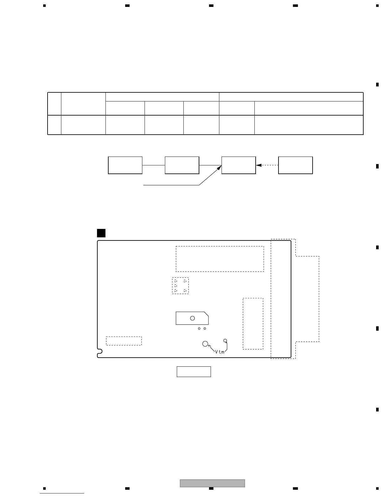
MPX SG FM SG
PRODUCT
DC
Voltmeter
L201
IC201
pin 21
pin 23
FM/AM TUNER UNIT
A
SIDE B
Step
No.
Adjustment
Title
ANT. Input level and signal condition
Adjustment
Input Level
(dBµV)
Adjust
point
Contents
Frequency
(MHz)
Modulation
1
T-METER
Adjustment
98 OFF 80
L201
Adjust L201 so that the DC voltage between Pin
21 and Pin 23 of IC201 (Test point Vtm) gets
within 0 ± 50mV.
FM75Ω antenna terminal
Fig.6.5 Adjustment Wiring Diagram
Fig.6.6 Adjustment Point
6.2.1 AM TUNER SECTION
There is no adjustment in the AM tuner.
6.2.2 FM TUNER SECTION
Set the mode selector to FM BAND.
Connect the wiring as shown in Fig. 6-5.