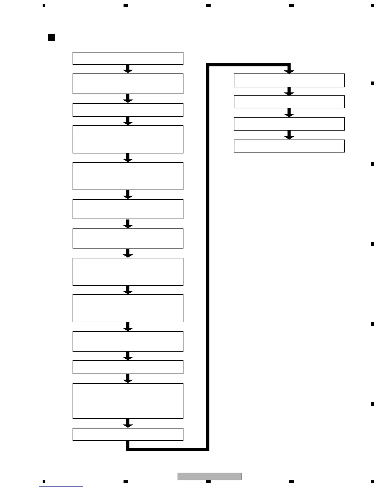
STANDBY
Power on operation by a user
(remote controller key or product key)
FL controller receives a message
[FL controller]
LCD lighting / outputs a power on signal
(POWER ON: "L"→"H")
[FL controller]
Release the reset for BACK END
(XRESET: "L"→"H")
[BACK END]
Accesses flash ROM and 64M SDRAM
[BACK END]
Accesses FRON END
[BACK END]
Request communication to the FL
controller (FP_ACK)
[FL controller]
Outputs the signal which can
communicate to BACK END (FP_XRDY)
BACK END – FL controller
communication
The opening picture output
[FRONT END]
Identifies the following:
• Slider positioning (INSIDE SW)
• Spindle FG stop
Disc detection (Focus control)
Spindle turn
Read ID information code
Various setting
The picture output
Flow chart from power on to the picture output