DA50S/DA55S/DA70S/DA75S AddressRight™ Printers Service Manual
5-3
Removal & Replacement • 5
DA50S/DA55S (WS51/WS56) Parts Removal
1. Remove operator side cover (see section 5.2).
2. Remove all cables. Starting clockwise from top right: P22, P10 (LAN),
P7 (USB), P13, P2 (red/white motor cable), P5, P6, P11, P23, P18, P3
(white ribbon cable), P4 (2nd white ribbon cable if color printer), and P9.
3. Remove 11 phlllips screws (circled in left photo below) holding board to
shield and remove board.
4. Remove grounding strap from bottom left corner and three bottom
screws (circled in right photo below) to remove grounding sheet.
1. Unfasten operator side cover (two phillips screws). Lift up printer slightly
to completely remove cover (two printer feet are captured by the cover)
2. From behind cover, unfasten display/keyboard cable (gray P9) and the
green grounding cable (see photo below).
3. Carefully peel back display overlay (from corner) on front of display.
4. Remove three phillips head screws (circled below) from underneath and
remove board from cover.
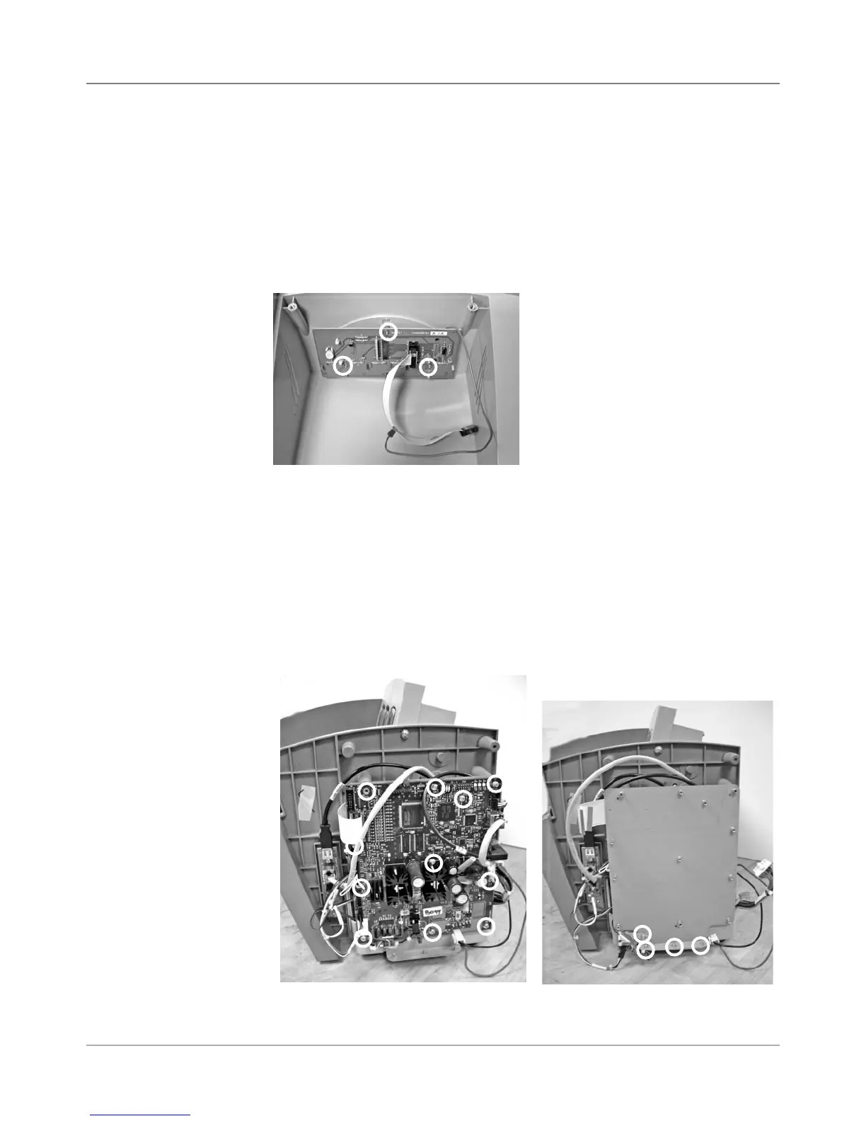
5.3 Display/
Keyboard
Display/Keyboard Board
(screw locations in circles)
Main Processor Board
(screw locations in circles)
5.4 Main
Processor
Board/
Grounding
Sheet
Assembly
Grounding Sheet Under
Main Processor Board
(screw locations in circles)