DA50S/DA55S/DA70S/DA75S AddressRight™ Printers Service Manual
5-17
Removal & Replacement • 5
DA70S/DA75S (WS71/WS76) Parts Removal
5.12 Display/
Keyboard
5.13 Main
Processor
Board/
Grounding
Sheet
Assembly
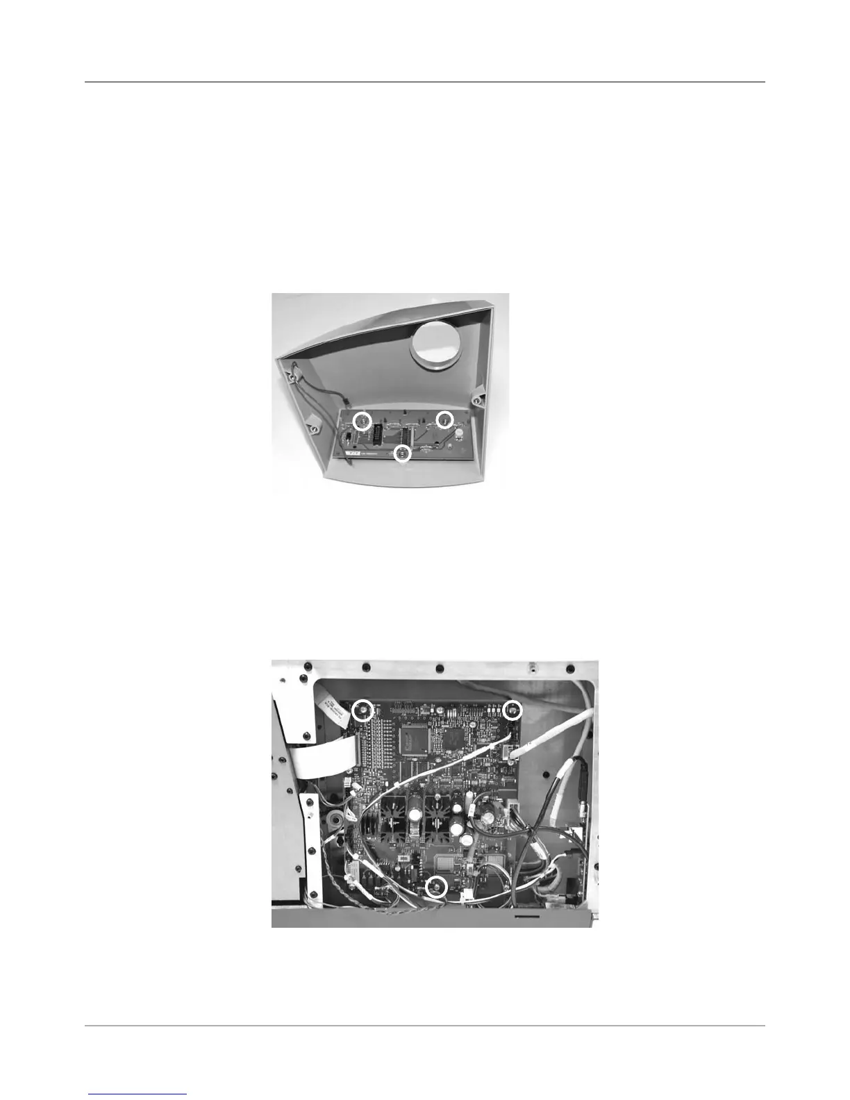
1. Remove three phillips screws holding control panel cover (two on one
side, one on the other).
2. Remove gray P2 and green ground cable (uses 9/64” allen) going to key-
board/control board.
3. Carefully peal back display overlay (from corner).
4. Remove three phillips head screws from underneath and remove board
from cover.
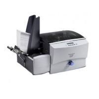
1. Remove non-operator side cover.
2. Remove all cables. Starting clockwise from top right: P22, P10 (LAN),
P7 (USB), P13, P2 (red/white motor cable), P5, P6, P11, P23, P18, P3
(white ribbon cable), P4 (2nd white ribbon cable if color printer), and P9.
3. Remove three screws (see photo below, circled) going through board and
grounding plate.
Display/Keyboard Board
(screw locations in circles)
4. Remove the nine additional screws to remove board from grounding
plate.