10
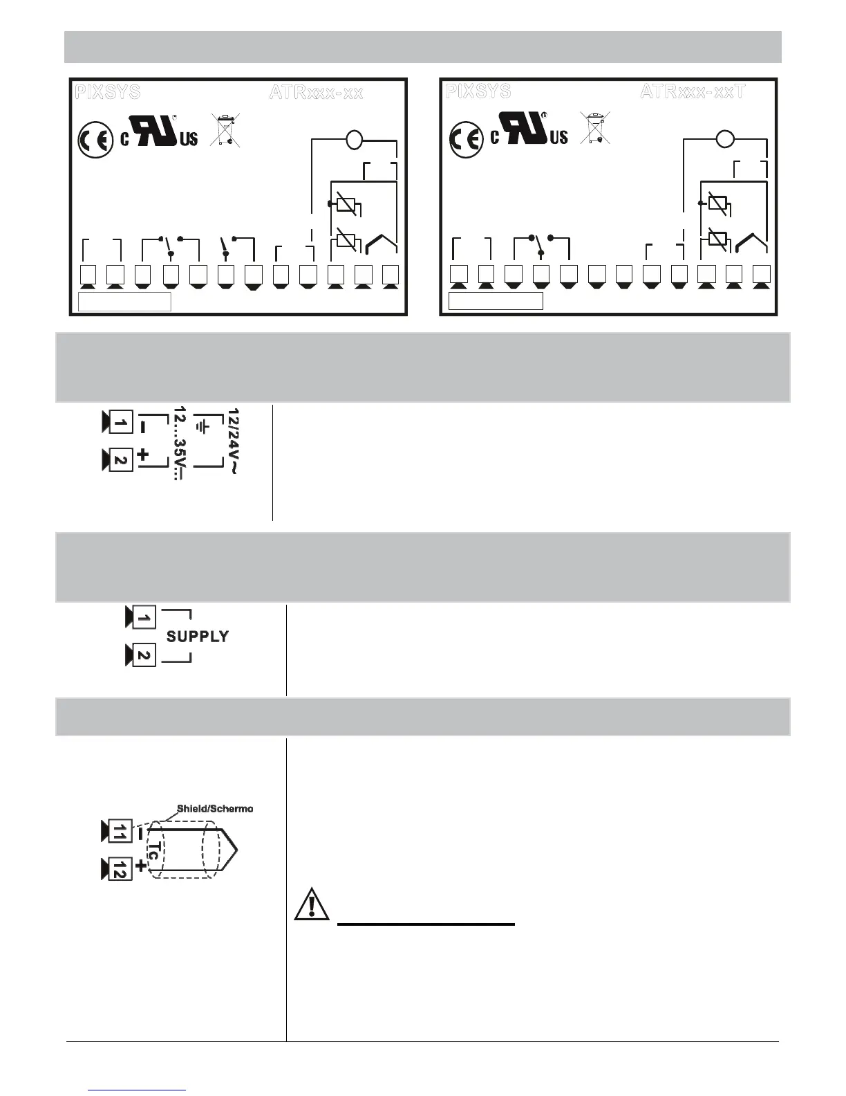
10 - WIRING DIAGRAM ATR121 / ATR141
PIXSYS
10A 230V
Co sf 1
3A 230V
Cosf 0.8
Q1
PT C/ N T C
-
+
Tc
+VDC
S SR
1 234
5
6789
10 11 1 2
-
+
I
V/I
+
-
PT/NI100/1K
2 wire 4/20mA
Po we r
M emory1
-
+
ATRxxx- xxT
-
+
RS485
SUPPLY
PIXSYS
10A 230V
Co sf 1
3A 230V
Cosf 0.8
Q1
PT C/ N T C
-
+
Tc
+VDC
SSR
1 234
5
6789
10 11 12
-
+
I
V/I
+
-
PT/NI100/1K
2 wire 4/20mA
Po wer
5A 230V
Co sf 1
1A 230V
Cosf 0.8
Q2
M emory
1
ATRxxx- xx
-
+
SUPPLY
10.1 Low tension power supply 12/24 Vac-Vdc
Models: ATR121-AD , ATR141-AD
12…24Vac ± 10% 50/60Hz
12…35Vdc
**Code “T” with serial communication
ONLY 12…35Vdc
10.2 Power supply 24/115/230 Vac
Models: ATR121-A-B-C , ATR141-A-B-C
24Vac ± 10% 50/60Hz
230Vac ± 10% 50/60Hz
115Vac ± 10% 50/60Hz
10.3 AN1 analogue input
For thermocouples K, S, R, J
• Comply whit polarity
• When extending thermocouples be
sure to use the correct
extension/compensating cable
Only model AD
To assure optimal operation of the device,
use ground-isolated sensors. Otherwise
use single isolated transformers for each
controller