22 ATR401 - User manual
Updating Memory Card
To update the memory card values, follow the procedure described in the
rst method, setting display 2 to so as not to load the parameters on
controller
1
.
Enter con guration level by password and change at least one parameter
(display will start ashing). Exiting con guration mode, the settings will be
automatically saved on Memory card.
9 LATCH ON Functions (only AI1)
For use with input (potentiometer 6 KΩ) and (potentiometer
150 KΩ) and with linear input (0…10 V, 0...40 mV, 0/4…20 mA), it is possible
to associate start value of the scale (parameter 6 ) to the minimum
position of the sensor and value of the scale end (parameter 7 ) to the
maximum position of the sensor (parameter 8 con gured as ).
It is also possible to x the point in which the controller will display 0 (however
keeping the scale range between and ) using the “virtual zero”
option by setting or in parameter 8
If you set the virtual zero will reset after each activation of the device;
if you set the virtual zero remains xed once tuned.
To use the LATCH ON function, rst choose the selected option on parameter
2
Then refer to the following table for the calibration procedure:
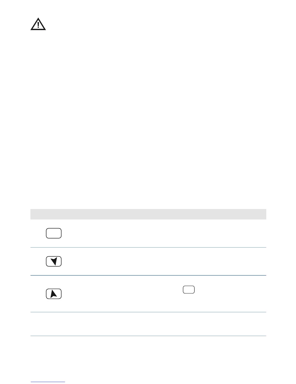
Press Display Do
1
FNC
Exit parameters con guration.
Display 2 visualizes writing
Place the sensor on minimum
operating value (corresponding
to
2
Store value on minimum.
Display shows
Place sensor on maximum
operating value (corresponding
to ).
3
Store value on max. Display
shows
To exit standard proceeding
press
FNC
.
For “virtual zero” setting, place
the sensor to zero point.
1
If on activation the controller does not display it means no data have been saved on the
memory card, but it is possible to update values.
2
The tuning procedure starts by exiting the con guration after changing the parameter.