10 ATR401 - User manual
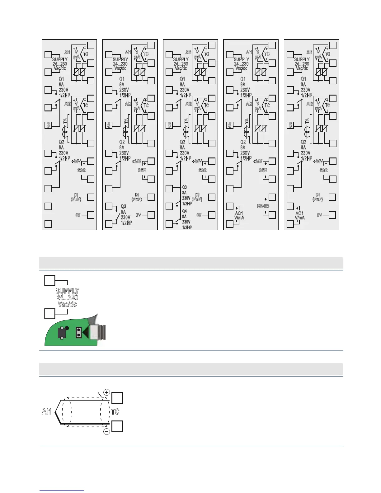
5.1 Wiring diagram
8
9
10
18
19
20
Q1
8A
230V
1/2HP
Q2
8A
230V
1/2HP
SUPPLY
24...230
Vac/dc
1
2
3
4
5
6
7
11
12
13
14
15
16
17
+24V
SSR
TC
V
mA
AI1
TC
V
mA
TA
AI2
DI
(PnP)
0V
Q3
8A
230V
1/2HP
8
9
10
18
19
20
Q1
8A
230V
1/2HP
Q2
8A
230V
1/2HP
SUPPLY
24...230
Vac/dc
1
2
3
4
5
6
7
11
12
13
14
15
16
17
+24V
SSR
TC
V
mA
AI1
TC
V
mA
TA
AI2
DI
(PnP)
0V
8
9
10
18
19
20
Q1
8A
230V
1/2HP
Q2
8A
230V
1/2HP
SUPPLY
24...230
Vac/dc
1
2
3
4
5
6
7
11
12
13
14
15
16
17
+24V
SSR
TC
V
mA
AI1
TC
V
mA
TA
AI2
Q3
8A
230V
1/2HP
Q4
8A
230V
1/2HP
DI
(PnP)
0V
8
9
10
18
19
20
RS485
Q1
8A
230V
1/2HP
Q2
8A
230V
1/2HP
AO1
V/mA
SUPPLY
24...230
Vac/dc
1
2
3
4
5
6
7
11
12
13
14
15
16
17
+24V
SSR
TC
V
mA
AI1
TC
V
mA
TA
AI2
8
9
10
18
Q1
8A
230V
1/2HP
Q2
8A
230V
1/2HP
AO1
V/mA
SUPPLY
24...230
Vac/dc
1
2
3
4
5
6
7
11
12
13
14
15
16
17
+24V
SSR
TC
V
mA
AI1
TC
V
mA
TA
AI2
19
20
DI
(PnP)
0V
ATR401-22ABC ATR401-23ABC ATR401-24ABC ATR401-22ABC-T ATR401-22ABC-D
Power
SUPPLY
24...230
Vac/dc
1
2
JP4
TS1
C21
Switching power supply with extended range; 2
selections:
• 24 Vac/dc ±15% with Jumper insertion JP4;
• 115…230 Vac/dc ±15% without Jumper JP4;
50/60 Hz – 5,5 VA (with galvanic isolation).
Analogue Input AI1
11
12
AI1
TC
Shield/Schermo
For thermocouples K, S, R, J.
• Comply with polarity.
• For possible extensions, use a compensated wires
and terminals suitable for the thermocouples used.
• When shielded cable is used, it should be
grounded at one side only.