ATR401 - User manual 11
11
12
13
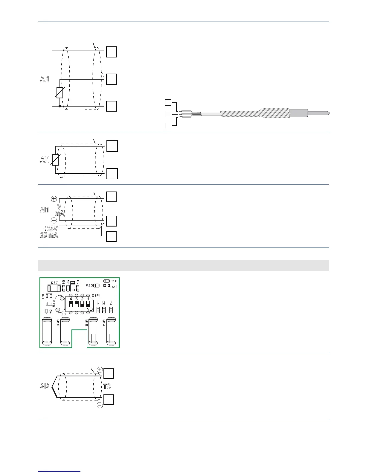
AI1
PT/NI100
Shield/Schermo
Rosso
Red
Bianco
White
Rosso
Red
For thermoresistances PT100, NI100.
• For a three-wires connection use cables with the
same diameter.
• For a two-wires connection short-circuit terminals
11 and 13.
• When shielded cable is used, it should be
grounded at one side only.
13
12
11
RED/ROSSO
RED/ROSSO
WHITE/BIANCO
12
13
AI1
Shield/Schermo
PTC/NTC
For thermoresistances NTC, PTC, PT500, PT1000
and linear potentiometers.
When shielded cable is used, it should be grounded
at one side only.
11
12
17
AI1
V
mA
+24V
25 mA
Shield/Schermo
For linear signals Volt / mA.
• Comply with polarity.
• When shielded cable is used, it should be
grounded at one side only.
Analogue Input AI2
To enable the second analogue input, set the dip
switches as indicated in the gure.
In this con guration input T.A. (current transformer)
is not available.
14
15
AI2
TC
Shield/Schermo
For thermocouples K, S, R, J.
• Comply with polarity.
• For thermocouples extensions, make sure to use
the correct extension/compensating cable.
• When shielded cable is used, it should be
grounded at one side only.