12 ATR401 - User manual
14
15
16
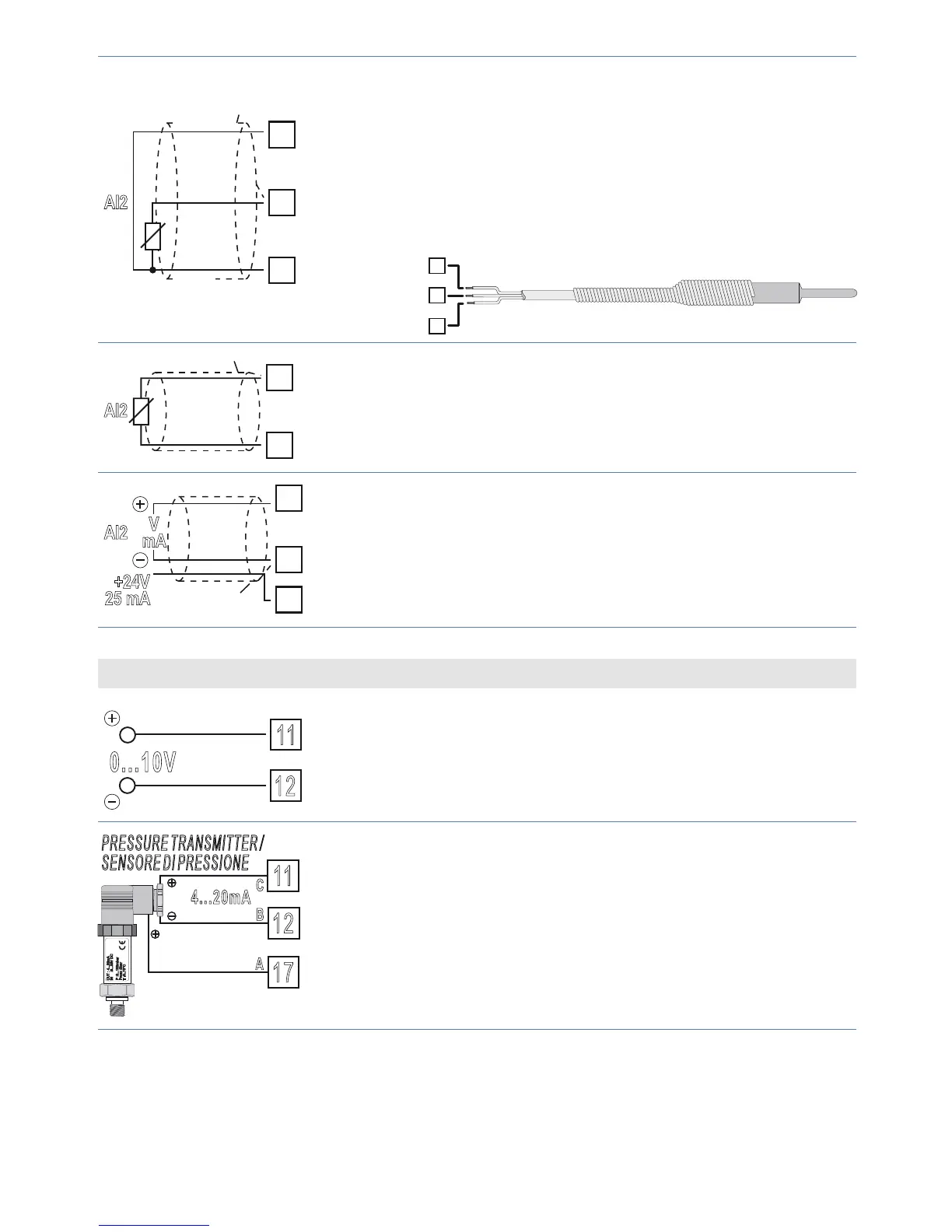
AI2
Shield/Schermo
PT/NI100
Rosso
Red
Bianco
White
Rosso
Red
For thermoresistances PT100, NI100.
• For a three-wires connection use cables with the
same diameter.
• For a two-wires connection short-circuit terminals
14 and 16.
• When shielded cable is used, it should be
grounded at one side only.
16
15
14
RED/ROSSO
RED/ROSSO
WHITE/BIANCO
15
16
AI2
Shield/Schermo
PTC/NTC
For thermoresistances NTC, PTC, PT500, PT1000
and linear potentiometers.
When shielded cable is used, it should be grounded
at one side only.
14
15
17
V
mA
Shield/Schermo
AI2
+24V
25 mA
For linear signals Volt / mA.
• Comply with polarity.
• When shielded cable is used, it should be
grounded at one side only.
Examples of connection for linear input AI1
12
11
0...10V
For linear signals 0….10 V.
Comply with polarity.
PRESSURE TRANSMITTER /
SENSORE DI PRESSIONE
P :0...100mbar
Pmax :3bar
T :0..70°C
OUT : 4...20mA
IN :9...33V DC
17
12
11
B
C
A
4...20mA
For linear signals 0/4….20 mA with three-wires
sensors.
Comply with polarity:
C = Sensor output
B = Sensor ground
A = Sensor supply (24 Vdc / 25 mA)