ATR401 - User manual 13
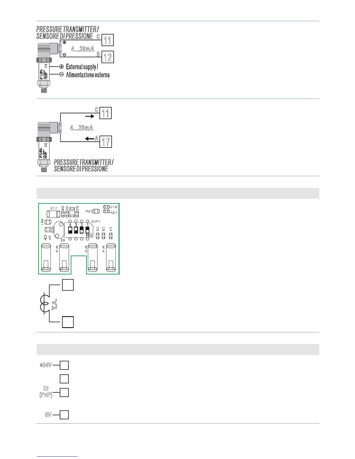
External supply /
Alimentazione esterna
P :0...100mbar
Pmax :3bar
T :0..70°C
OUT : 4...20mA
IN :9...33V DC
PRESSURE TRANSMITTER /
SENSORE DI PRESSIONE
12
11
C
B
4...20mA
For linear signals 0/4..20 mA with external power
supply for sensor.
Comply with polarity:
C = Sensor output
B = Sensor ground
P :0...100mbar
Pmax :3bar
T :0..70°C
OUT : 4...20mA
IN :9...33V DC
11
17
C
A
PRESSURE TRANSMITTER /
SENSORE DI PRESSIONE
4...20mA
For linear signals 0/4..20 mA with two-wires sensors.
Comply with polarity:
C = Sensor output
A = Sensor supply (24 Vdc / 25 mA)
T.A. Input (Current transformer)
15
16
T.A.
To enable T.A. input, set the dip switches as
indicated in the gure.
In this con guration it is possible to set on
parameter 11 .
• Input for current transformer 50mA
• Sampling time 100 ms.
• Con gurable by parameters.
Digital input (not available on ATR401-22ABC-T)
19
20
17
+24V
DI
(PnP)
0V
Digital input (par. 84 ).
Short-circuit pin “DI” (19) and pin “+24 V” (17) to
enable digital input.