10 ATR 621 - User manual
4 Electrical wirings
Although this controller has been designed to resist noi-
ses in an industrial environments, please notice the fol-
lowing safety guidelines:
• Separate control lines from the power wires.
• Avoid the proximity of remote control switches, elec-
tromagnetic meters, powerful engines.
• Avoid the proximity of power groups, especially those
with phase control.
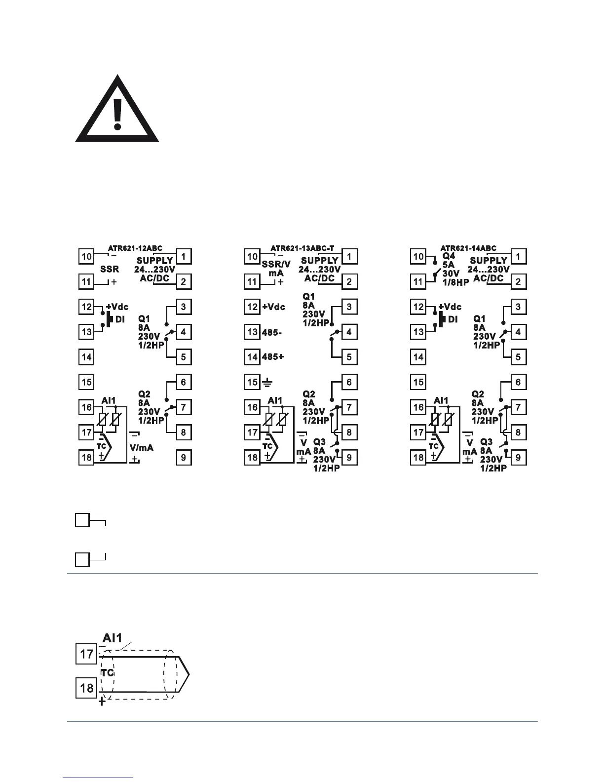
4.1 Wiring diagram
Power supply
4611-:t"-*.&/5";*0/&
24...230
Vac/dc
1
2
Switching supply with extended range
24…230 Vac/dc ±15% 50/60Hz – 5,5VA
Analogue input AI1
Shield/Schermo
For thermocouples K, S, R, J, E, N.
• Comply with polarity
• For extensions make sure to use the correct
extension/compensating cable
• When shielded cable is used, it should be
grounded at one side only.
 Loading...


