ATR 621 - User manual 15
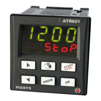
5.1 Numeric indicators (display)
1
Usually visualizes process value, it may visualize also
setpoint value, time elapsed from cycle start, number of
operating step or the percentage value of the command
output. During con guration it visualizes the value of
entering parameter.
2
Visualization can be customized with setpoint, time elap-
sed from cycle start or number of operating step. During
con guration it visualizes the value of entering parameter.
5.2 Meaning of Status Lights (led)
3 C1
On when command output is active. For open /close logic:
on during valve opening.
4
C2 For open/ close logic: on during valve closing.
5
A1 On when alarm 1 is active.
6
A2 On when alarm 2 is active.
7
A3 On when alarm 3 is active.
8
MAN On when “Manual” function is active
9
TUN On when controller is executing an auto-tuning cycle.
10
REM On when serial communication is in progress.
11
RUN
On when controller is operating a cycle or is thermocon-
trolling.
5.3 Keys
12
• In con guration allows to scroll and modify parameters.
• Scroll cycles to be started or modi ed.
• In cycle programming allows to modify time and setpoint
parameters.
• Modi es setpoint in function.
• Modi es command output percentage in . function.
• Allows a quick advancement of the cycle when it is in “START”.

 Loading...