ATR 621 - Manuale uso 55
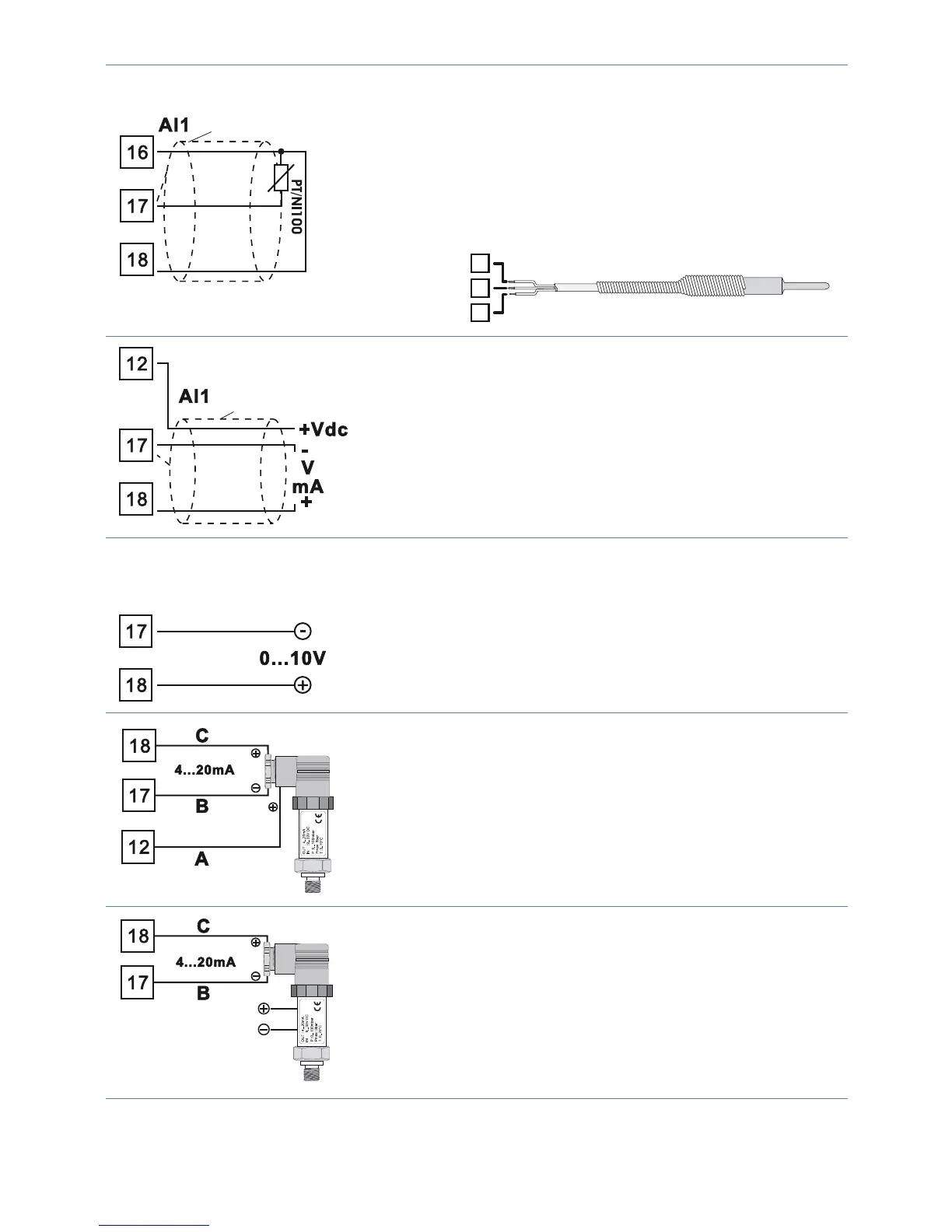
Shield/Schermo
Per termoresistenza PT100
• Per il collegamento a tre li usare cavi della
stessa sezione.
• Per il collegamento a due li cortocircuitare i
morsetti 16 e 18.
• Quando si usa cavo schermato, lo schermo deve
essere collegato a terra ad una sola estremità
16
17
18
RED/ROSSO
WHITE/BIANCO
RED/ROSSO
Shield/Schermo
Per segnali normalizzati in corrente e tensione
• Rispettare la polarità
• Quando si usa cavo schermato, lo schermo deve
essere collegato a terra ad una sola estremità
Esempi di collegamento per ingressi normalizzati AI1
Per segnali normalizzati in tensione 0….10V
• Rispettare le polarità
PRESSURE TRANSMITTER
Per segnali normalizzati in corrente 0/4….20mA
con sensore a tre li
• Rispettare le polarità
C = Uscita sensore
B = Massa sensore
A = Alimentazione sensore (12Vdc/25mA)
PRESSURE TRANSMITTER
SENSORE DI PRESSIONE
EXTERNAL SUPPLY
ALIMENTAZIONE ESTERNA
Per segnali normalizzati in corrente 0/4..20mA con
sensore ad alimentazione esterna
• Rispettare le polarità
C = Uscita sensore
B = Massa sensore
 Loading...


