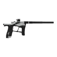
FIG-1
A
10
INTRODUCTION
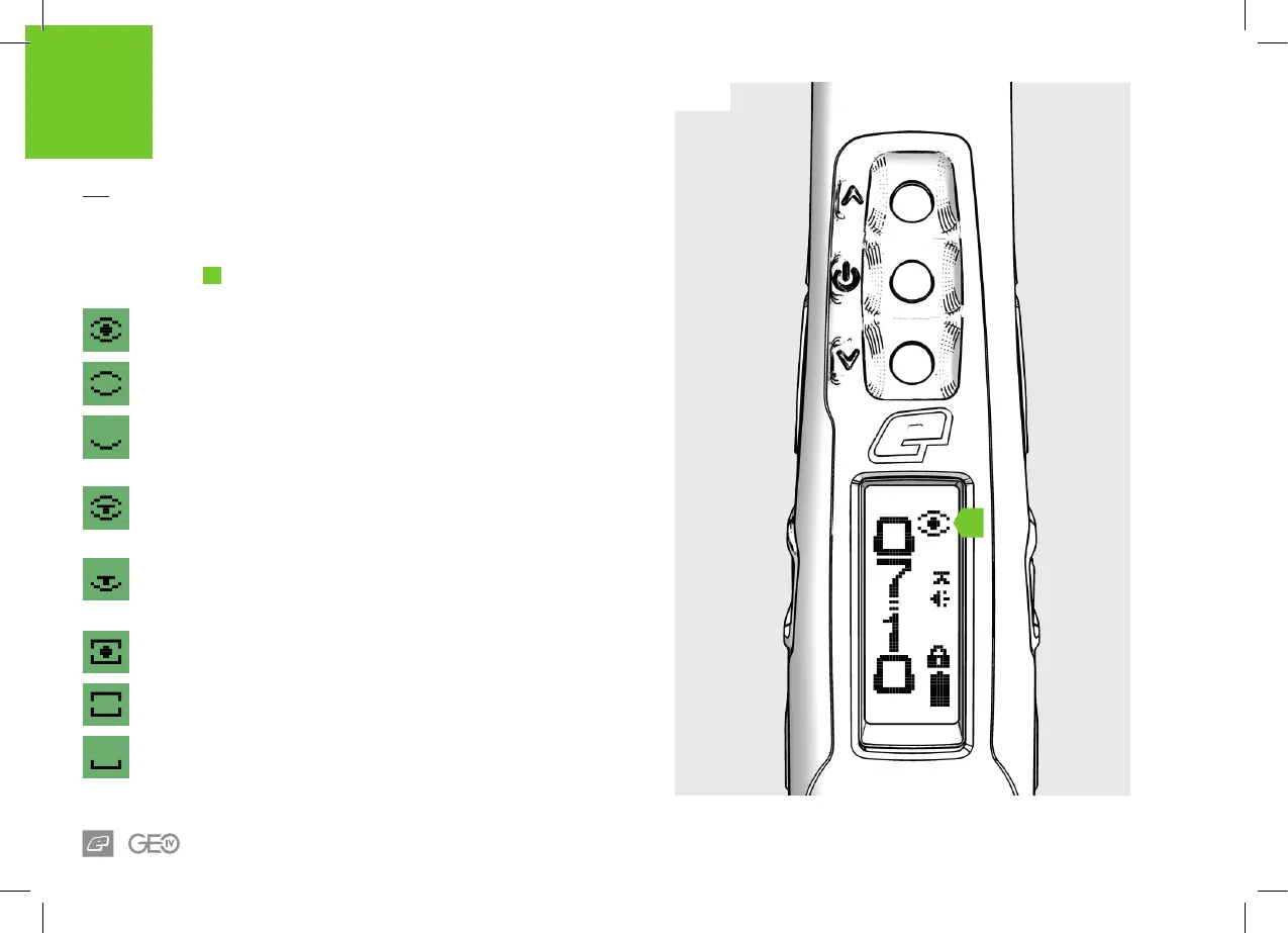
BREECH SENSOR
(BS) INDICATOR
FIG-1
The BS indicator
A
displays the various states of the breech sensor.
BS enabled and a ball is detected
The marker can be red up to the selected rate of re.
BS enabled and NO ball is detected
The marker cannot be red.
BS disabled
The marker can be red up to the rate of re set by the BS
OFF ROF parameter (see page 27).
BS enabled in training mode
Training mode is enabled and simulates ring up to the
selected rate of re.
BS disabled in training mode
Training mode is enabled and simulates ring up to the rate of
re set by the BS OFF ROF parameter.
BS fault has been cleared and a ball is detected
The marker can be red up to the selected rate of re.
BS fault has been cleared and NO ball is detected
The marker cannot be red.
BS fault detected
Breech Sensor is temporarily disabled. The marker can be
red up to a rate of re that is 2bps lower than that set by the
BS OFF ROF parameter.